Summary of Interfacing of Push Button with Atmega16
This tutorial explains configuring Atmega16 DDR registers for input/output, interfacing a push button to read pin states, debouncing the switch with a 100 ms delay, and controlling an LED based on the button. It includes example code, wiring guidance (button between A0 and ground, LED on D0 to Vcc), notes about Proteus simulation limitations, and recommendation to test on actual hardware.
- Atmega16 microcontroller
- Push button
- LED
- Resistor for LED (implied)
- Wires/jumper cables
- Power supply or Vcc
- Development board (Atmega16 dev board) or breadboard
In this tutorial, I will walk through interfacing a push button with the Atmega16 microcontroller. It is assumed the reader has some familiarity with basic microcontroller concepts from my previous post on blinking an LED.
Before connecting a push button, we must understand how to configure ports for input and output. Ports need to be set as inputs to accept signals, and outputs to provide signals. This is done by writing an appropriate value to the DDR (Data Direction Register).
If a port is set as an input, the microcontroller can read the logic level on that pin. As an output, it can control the logic level. Proper DDR configuration is crucial for interfacing any external component to collect input or deliver output.
This post will demonstrate writing to the DDR to set a port as an input. Then we can interface a push button and program the microcontroller to respond when the button is pressed. Let’s get started!
For declaring an input port
DDRB=0;         //Decimal 0, giving all the bits of DDRB register 0 value.
DDRB=0x00;  //Hexadecimal
DDRB=0b00000000;// binary
For declaring an output port
DDRB=255; //Decimal number, setting all the bits of DDRB register high DDRB=0xff; // Hexadecimal, DDRB=0b11111111; // Binary value
We can declare an individual pin as an input as well as an output pin.
DDRB=127; //If you put that value to DDRB register, Pin7 would be an input pin and //rest of the pin would be output pin. DDRB=0x7f; //Representing the same with hexadecimal numbers DDRB=0b01111111; //Representing the same with binary. DDRB=1<<2; // Using shift operator to convert 2nd pin of port B as an output pin.
Push Button
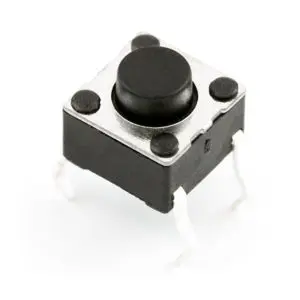
A push button functions similar to a basic switch, allowing the user to provide input to the microcontroller. In this post, we will control an LED using a push button interface. While an abstract concept, do not fret – it is indeed possible!
To interface the push button with the Atmega16, we must declare a port as an input. Then, continuously monitor the status of the connected pin. Pressing or releasing the button will change the pin value. Based on the pin’s status, we can command the LED to turn on or off accordingly.
When the button is pressed, the pin reads low and the LED will light. Releasing returns the pin high and turns off the LED. By reading the button pin and controlling the LED pin in code, we create a simple press-to-illuminate interaction.
Stay tuned as we work through setup and programming to allow button pressing to toggle an LED on and off. I hope this brief introduction leaves you eager rather than skeptical of the process!
The program logic is quite simple and direct. We will monitor the status of the designated input pin. A reading of ‘1’ indicates the button is pressed, so we turn on the LED. Conversely, if the pin reads ‘0’, it means the button has been released and we must turn off the LED.
By continually checking the pin value and conditionally controlling the LED pin, we can respond to button presses in real-time. When pressure is applied to close the button circuit, the input pin goes high and illuminates the LED. Releasing the button opens the circuit, dropping the pin low and turning off the light.
Effectively, we are using the pin status to determine the button state – pressed or released. From there, a single command changes the LED output accordingly. The program elegantly translates mechanical button input to visible light feedback via straightforward digital logic.
#include <avr/io.h>
#include <util/delay.h>
int main(void)
{
DDRA=0x00;// for input port-LED
DDRD=0xff;// for output port-Switch
while(1)
{
if(PINA==0x01)// checking the status of PIN, if it is ‘1’, turns on the LED
{
_delay_ms(100); // for debouncing of switch
PORTD=0x01; // Turning on the LED
}
else if(PINA==0x00)// checking the status of PIN, if it is ‘0’, turns off the LED
{
_delay_ms(100); // For debouncing of switch
PORTD=0x00;// Turning off the LED
}
}
}
Debouncing of Switch
It is necessary to perform button debouncing because without it, multiple unintended presses may be processed from a single click. For instance, if no delay is introduced and the button is pressed, it could register as several sequential presses rather than one smooth action.
To remedy this, a brief delay must be added. I have opted for a 100ms (millisecond) pause to allow the button circuit time to settle after each press or release. This debouncing period prevents transient electrical noise from erroneously registering as extra button activations.
By introducing this short delay, we ensure clean detection of distinct press/release cycles rather than erroneous double or triple counts. The end result is a user experience where the software accurately interprets every intentional button press as a singular registered input.
While a schematic is provided for reference, simulation of this program in Proteus may not behave exactly as intended. Proteus is not always able to perfectly emulate microcontroller code. This issue confirms the value of using an actual development board for testing.
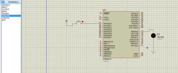
The programming concept shown here has been successfully verified on my Atmega16 board. To recreate it, connect a push button between the chosen microcontroller input pin (A0 in this case) and ground. Also connect an LED cathode to the selected output pin (D0) with anode to Vcc.
Once the microcontroller is programmed with this code, pressing the button should toggle the LED as expected. While Proteus can provide a starting point, sometimes the most robust validation comes from hardware implementation. Development boards simplify the process of iterating code in real systems.
If you have access to an Atmega16 dev board, try implementing this there‐pressing the physical button should reliably control the LED according to the program logic. Let me know if any part of the hardware setup or programming requires further explanation.
- How do you set a port as input on Atmega16?
Write 0 to the DDR register for that port, e.g., DDRB=0 or DDRB=0x00. - How do you set a port as output on Atmega16?
Write 1s to the DDR register for that port, e.g., DDRB=255 or DDRB=0xff. - Can you configure an individual pin as input or output?
Yes; set DDR with the appropriate value or use bit shift like DDRB=1<<2 to affect a specific pin. - What is the basic logic for reading a push button and controlling an LED?
Continuously read the input pin: if it reads 1 turn on the LED, if it reads 0 turn off the LED. - Do I need debouncing for the push button?
Yes, the tutorial uses a 100 ms delay to debounce the switch and avoid multiple unintended presses. - How should the push button and LED be wired in this example?
Connect the push button between input pin A0 and ground; connect the LED cathode to output pin D0 and the LED anode to Vcc (with a resistor implied). - Will Proteus perfectly emulate this program?
No, Proteus may not always emulate microcontroller behavior perfectly; the author verified the program on real hardware. - What code libraries are used in the provided program?
The code includes avr/io.h and util/delay.h.