This Instructable is about making a Google-Calendar-controlled irrigation programmer based on a ESP8266.
How to use it?Add a task to your Google Calendar and the irrigation of your garden/lawn will start when the event begins and stop when it ends!
You love this Ible? Vote here: https://www.instructables.com/contest/Microcontroller2017/
Why I invented that? I don’t like the interface of cheap irrigation programmers, the irrigation parameters are not flexible enough and it can’t be controlled remotely. I wanted a cheap wifi irrigation programmer but I didn’t want to build the entire UI for the ESP8266, I preferred to be able to change the irrigation planning from anywhere with simple means. I decided to have the ESP polling one of my Google Calendars, with events to turn on and off the valve at the correct timing.
How is this made possible? A ESP8266 connects to your Google Calendar via your home Wifi (using a Google Script) and commands a solenoid valve.
What skills are needed? Basic electronics and software programming skills.
What tools are needed? Basic electronics tools, a RS232 USB programmer and a computer.
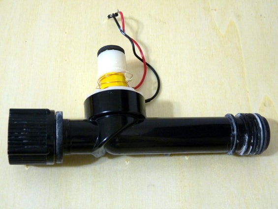
I had a basic irrigation programmer that was useless because its display was broken. I scavenged the solenoid valve and the enclosing for this project.
Step 1: Parts
We will need several electronic parts:
- 3 x Capacitors (22µF electrolytic, 0.1µF ceramic, 4700µF electrolytic)
- 1 x DC motor driver (DRV8872 in this case)
- 1 x ESP8266 (version ESP07)
- 1 x 3.3V Voltage regulator (LT1529-3.3 for instance)
- 1 x 12V CC 1.5A charger
- 1 x Female plug (same size as the charger’s plug)
- 1 x Prototyping board
- 1 x Latching solenoid valve (scavenged from an Orbit 58874N)
- 3 x Momentary push buttons
- 1 x Rocker switch
- 3 x Straight male headers
- Some wires
Some basic tools: USB RS232 programmer, pliers, soldering iron, etc.
And a Google Account.
The fact that the valve is a “latching” type (also known as “bi-stable”) is important. We can drive it with a DC motor driver/H-bridge. Main advantage: it doesn’t require energy to remain open or closed. Main drawback: it is not fail-safe, if for some reason the power goes off then the water will continue to flow if the valve was open (we will add a safety procedure in the ESP’s firmware to mitigate that risk).
Step 2: Build an Adapter for the 8-pin SOP Circuit
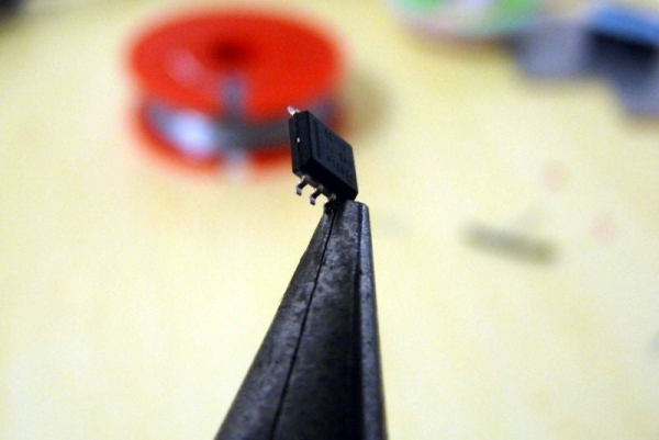
The DC motor driver I have is in a 8-pin SOP package, it is very tiny and I need to build a way to connect it to my prototype board. This is a very delicate process so take your time and be patient.
- Flatten the chip’s pins
- Flatten the tip of a resistor wire
- Bend the flattened end
- Solder it to the heat dissipator/sink of the chip
- Cut and solder the wire to the GND of your board
- For each chip’s pin, repeat the process
Step 3: Build the Circuit
Solder the parts as illustrated (explanations below).
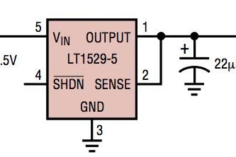
Connect the voltage regulator (datasheet) with basic components as follow:
- VIN pin to 12V CC power source
- OUTPUT pin to SENSE pin
- GND pin to board’s GND
Add a 22µF capacitor between OUTPUT and GND as close to the regulator as possible.
Connect the driver (datasheet) with basic components as follow:
- GND pin to board’s GND
- PPAD (heat sink) to board’s GND
- VM pin to 12V CC power source
- OUT1 pin to Solenoid red wire
- OUT2 pin to Solenoid black wire
- ISEN to board’s GND
Add the bulk capacitor (4700µF) between VM and GND (watch out the polarity) as close to driver’s VM pin as possible. Add the 0.1µF capacitor in parallel to the bulk one.
Connect the ESP (documentation) with the switch and buttons as follow:
- One push button between GPIO12 and 3.3V
- One push button between GPIO13 and 3.3V
- One rocker switch between GPIO00 and GND
Use the headers to have an easy access to ESP’s Rx, Tx and GND.
Connect the ESP with the voltage regulator as follow:
| ESP8266 | LT1521CST-3.3 |
|---|---|
| VCC | OUTPUT |
| GND | GND |
Connect the ESP with the driver as follow:
| ESP8266 | DRV8872 |
|---|---|
| GND | GND |
| GPIO04 | nFAULT |
| GPIO12 | IN1 |
| GPIO13 | IN2 |
Don’t forget to connect ESP’s GPIO16 pin to its RST pin (internal wakeup).
Step 4: Do Some Preliminary Tests
Connect the charger and push one by one the momentary buttons. You should hear a click, that is the solenoid actuating on the valve.
As we probably don’t know in which state the valve is closed or open we will need to perform some tests. Try to blow some air through the valve after having pushed and released one of the two buttons. If the air goes through it means that this button is the one that opens the valve. Repeat the process with the other button to clear any assumption.
Take note of the ESP pin to which the open button is connected, and the one that closes the valve too. We will use it to adjust the ESP’s firmware.
Step 5: Create a Dedicated Google Calendar
Many people have a Google Account. This includes the Google Calendar viewer. There you can create as many calendar as you want to.
Create a new calendar dedicated to our irrigation system:
- go to https://calendar.google.com and log in
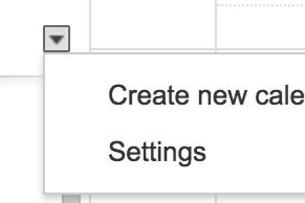
- click on the arrow close to “My calendars” and select “Create new calendar”
- name this calendar as you wish but keep that name somewhere as we will need it in the next step. “Irrigation” is a good name
- make sure that the time zone is correct according to your irrigation system location
- click on “Create Calendar”
Step 6: Create a Google Script
A Google Script is a way to create an bridge between a Google product, here your calendar, and outside world.
The Script will be the service we are going to poll to obtain the next events date and duration.
To have access to Google Scripts App you need to:
- Go to https://drive.google.com and log in
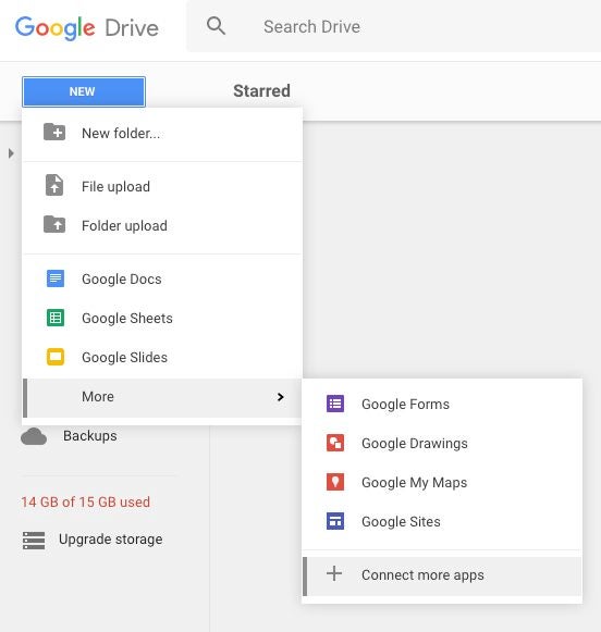
- Click on New > More > + connect more apps
- In the search box type “scripts” and hit return
- Click the “connect” button of the first result
- Back in Drive, click on New > More > Google Apps Script
- Copy and past the script from my Github: https://github.com/ClemRz/GCalendar-Irrigation
- Change the value of _calendarName with your irrigation-dedicated calendar’s name
- Click on save and name this script as you wish
- Click on Run > doGet
- An authorisation popup should show up, click on “Review Permissions” then “Allow”
- Click on Publish > Deploy as web app…
- Fill the fields as in the screenshot and hit “Deploy”
- Copy the url that is provided
You can also change the _checkInRate value which corresponds to the polling rate.
If you want to have a more reactive system, for instance that would detect a newly added event in the minute, change this variable to a lower value. The main drawback of having low values is that your ESP is going to have to poll more frequently i.e. using more bandwidth and more energy.In the other hand, if you don’t care about reactiveness but want a more energy efficient system, increase this value.
Note: if you change something in your script after publishing you can test using the dev. url in the Deploy window (“Test web app for your latest code.”). But the changes won’t be reflected to the public url until you update the deploy parameters with a new version (choose “new” instead of the version number).
Step 7: [Optional] Explanation of the Script
Here are some details about the Google Script.
this is where you adjust the name of your calendar and the polling rate:
  var _calendarName = 'Irrigation',
      _checkinRate = 5 * MINUTE;
doGet is the function that’s going to be called when you access the URL. It returns a text file (not an HTML one) with the result of the getOuput function:
return ContentService.createTextOutput(getOutput(_calendarName, _checkInRate));
The only goal of this function is to transform a JavaScript plain object (obtained by calling getResponse) into a JSON string:
return JSON.stringify(getResponse(calendarName, offset));
getResponse has the responsibility to create the plain object depending on several situations.
We first try to access to the calendar:
var cal = CalendarApp.getCalendarsByName(calendarName)[0];
If the calendar is not accessible for any reason (typo in the name for instance) then we return an error object:
  if (!cal) {
    return {status: 'error', message: 'Error, calendar "' + calendarName + '" does not exist.'};
  }
If we could open it, then we will get the events (items) that are soon to happen:
  var now = new Date(),
      later = new Date();

  later.setSeconds(now.getSeconds() + offset);

  var items = cal.getEvents(now, later),
      length = items.length,
      response = {};
If there are some events then we format the object accordingly:
  if (length){
    response = getEvent(items[0]);
    if (response.nextCheckIn > offset) response.nextCheckIn = offset;
We also adjust the next checkin rate so it is never greater than the polling rate.
If not, then we let the callee know that it needs to close the valve. Apart from indicating that an event has possibly ended, this also covers the case when the valve could have remained unintentionally open.
  } else {
    response = {closeValve: true, nextCheckIn: offset};
  }
We also let the callee know that everything went well by wrapping the response this way:
return {status: 'success', data: response};
The getEvent function basically do some maths and logic to determine when should happen the next checkin and if the valve needs to be opened or closed.
  var now = new Date(),
      title = item.getTitle(),
      startTime = item.getStartTime(),
      endTime = item.getEndTime(),
      fromNow = startTime - now,
      startsWithin = fromNow < 0 ? 0 : Math.round((fromNow)/1000),
      lasts = Math.round((endTime - (fromNow < 0 ? now : startTime))/1000),
      response = {title: title};
If the event already started then fromNow will be negative, we let the callee know that it needs to open the valve and the next checkin will correspond to the end of the event:
  if (fromNow <= 0) {
    response.openValve = true;
    response.nextCheckIn = lasts;
If the event is not started yet then we let the callee know that the valve needs to remain closed and the next checkin will be the starting date of the next event:
  } else {
    response.closeValve = true;
    response.nextCheckIn = startsWithin;
  }
We increment the nextCheckIn to prevent returning zero. If the ESP try to deep-sleep for 0 microseconds it would never wakeup by itself and it would be catastrophic:
  response.nextCheckIn++;

  return response;
Step 8: [Optional] Log the Interactions in a Spreadsheet in Order to Have Visual Control
If you want to make sure that your irrigation system is actually calling your Google Apps Script I recommend to do the following:
- Create a new spreadsheet in your Drive, name it “Irrigation”
- Rename the first sheet to “data”
- Add some headers to the first row: “Time” and “Data”
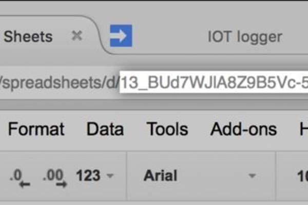
- Copy the ID of your spreadsheet, you will find it in the URL
- Add this function to your Script:function logToSpreadsheet(data) { var ss = SpreadsheetApp.openById(‘paste_here_your_spreadsheets_id’), sheet = ss.getSheetByName(‘data’); sheet.appendRow([new Date(), data]); }
- Modify the getOutput function:function getOutput(calendarName, offset) { var response = JSON.stringify(getResponse(calendarName, offset)); logToSpreadsheet(response); return response; }
- Publish a new version of your Script (Publish > Deploy as webapp > Project version: new > Update)
Wait for the ESP to call the Script, you should see a new row of data appended to the “data” sheet. This is the proof that your system is actually reaching the Script.
Source: Irrigation Using Google Calendar!