Summary of Keypad Door Lock using AVR Microcontroller – Atmega16
This article details a password-based keypad door lock using an ATMEGA16 microcontroller. It features a 4x4 matrix keypad for input, a seven-segment display for visual feedback, and a GSM module for SMS alerts. The system includes a relay to control a solenoid valve, a buzzer for security alarms after three failed attempts, and EEPROM storage to retain passwords during power loss.
Parts used in the Password Based Keypad Door Lock:
- ATMEGA16 microcontroller
- Seven segment display array
- 4X4 matrix keypad
- GSM module
- Relay
- Solenoid valve
- Buzzer
- EEPROM (internal to microcontroller)
- Proteus Simulation software
- Password Based Keypad Door Lock
In this article, a digitally secured lock based on password verification is explained. The system uses a seven segment display array to show the password, a matrix keypad to enter the numbers/password and operates a relay (to activate the solenoid valve) for locking and unlocking purpose. The system alarms through a buzzer if a wrong password is entered for 3 times continuously and an SMS is sent to a predefined contact number. The password can be changed whenever required, but only after correctly entering the present password. The password is stored in the EEPROM of the microcontroller so that, power failure or reset of the system does not affect the password recognition.
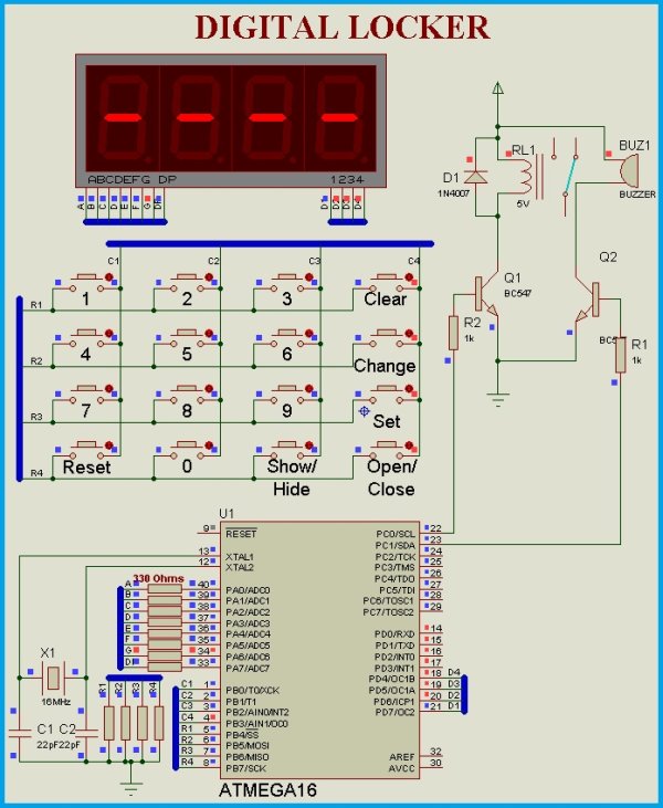
Circuit Diagram
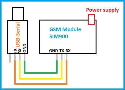
The system contains a seven segment display array, a 4X4 matrix keypad and a GSM module to send the status message. Based on these requirements, any microcontroller with 3 I/O ports and one UART peripheral is sufficient. In this article ATMEGA16 microcontroller is used. The circuit is developed using the Proteus Simulation software to demonstrate the operation. There is a real-time feature called the ‘Virtual Terminal’ in this software which is used in this article to send the SMS through a GSM Module connected to the computer.
The circuit diagram for connecting the GSM module to the computer is shown below. A detailed explanation on this procedure is provided in the article, “Virtual Comports in Proteus”.
The Matrix Keypad
In this circuit, a 4X4 matrix keypad is used to enter the password and to interact with the system. A function called the ‘get_key’ function is used to read the pressed key and this key information is passed to the ‘run_key_function’ which is a ‘switch statement’ with 16 cases, and is assigned with one case for each key. As there are 16 keys in the keypad, key value ranges from 1 to 16 and by default, the key value is set out of this range during initialization of the key variable. The ‘get_key’ function refreshes the columns and reads the rows for detecting the pressed key (if any). Whenever a key is pressed this default value is replaced by the currently pressed key. Now, the ‘run_key_function’ is executed and corresponding statements for the pressed key are executed. After execution of these statements, the display function is called until the pressed key is not released. Soon after the key is released, again the key value is set out of range. Below is the program code for the functions ‘get_key’. The ‘get_key’ function can be easily modified for keypads other than the 4X4 matrix.
The Display
As the password is of four digits, four seven segment LED’s are multiplexed. There is an option to show/hide the password while entering. The display function presented in this article uses one for loop and it can be modified easily if the number of digits is varied. If the show option=1 then digits are shown as they are and if show option=0 then the ‘G’ segment of the displays is enabled instead of the entire digit. The program code for the display function is shown below.
Read more: Keypad Door Lock using AVR Microcontroller – Atmega16
- How does the system alert when a wrong password is entered?
The system triggers a buzzer alarm if the wrong password is entered three times continuously and sends an SMS to a predefined contact number. - What component is used to enter the password?
A 4X4 matrix keypad is used to enter numbers and interact with the system. - Can the password be changed?
Yes, the password can be changed whenever required, but only after correctly entering the present password. - How is the password preserved during power failure?
The password is stored in the EEPROM of the microcontroller so that power failure or reset does not affect recognition. - Which microcontroller is utilized in this project?
The ATMEGA16 microcontroller is used because it has sufficient I/O ports and a UART peripheral. - How does the display handle password visibility?
The system allows showing or hiding the password; if hidden, the G segment is enabled instead of the entire digit. - What software was used to develop the circuit diagram?
The circuit was developed using Proteus Simulation software. - What function reads the pressed key on the keypad?
The get_key function is used to read the pressed key and refresh columns while reading rows.