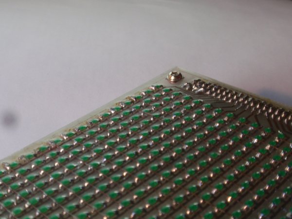
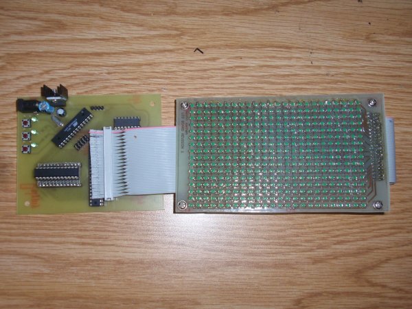
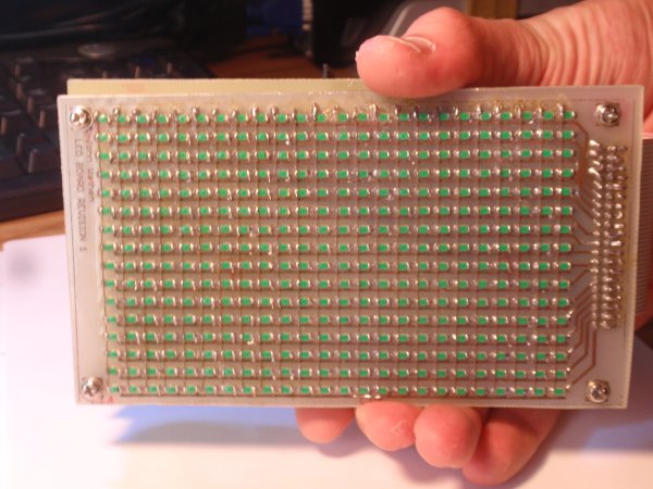
Last year in one of my classes we were required to make an ‘artefact’ or something that reflects the interests of the class. Most people make posters and the past two quarters that’s what my class did too. Posters however are static, usually boring, and don’t reflect that fact that everyone in the class is an EE major. We decided posters are for noobs and decided to go off the wall a little and make an LED matrix display. Lucky one of my friends John Wathen already had this beautiful 16×24 Green SMD LED matrix that he built back in high school.
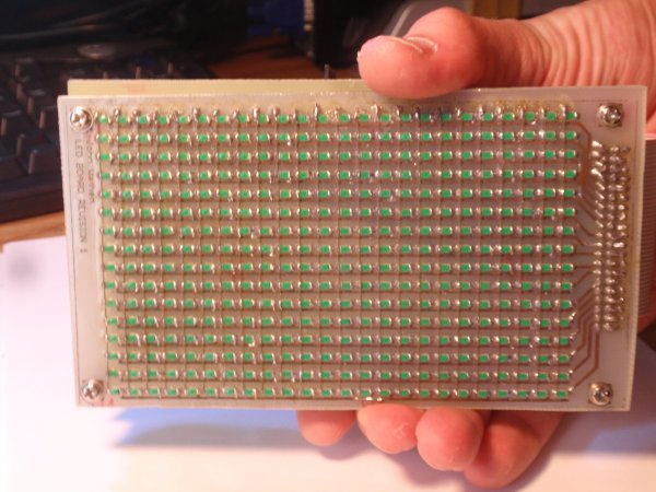
What we didn’t have however was a driver for it. The driver we choose to design was highly inspired from this one. The basic idea is that you use shift registers to sink the columns and a line driver of some sort to source the rows (we chose to use a Darlington array).
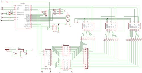
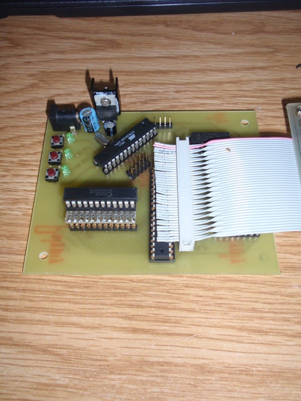
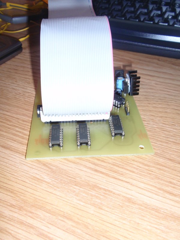
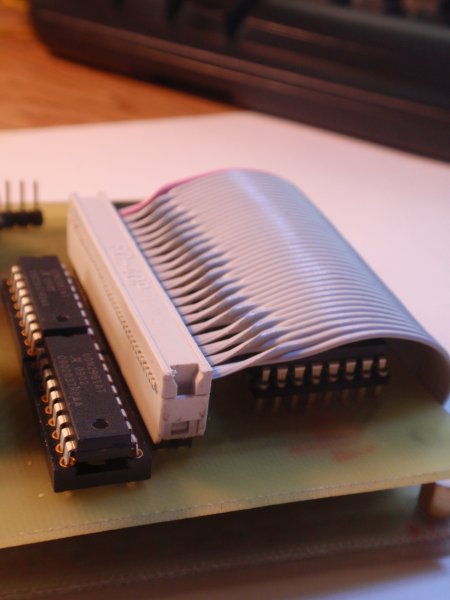
There where a lot of changes from the Instructables design that that we had to make however. The matrix in the Instructables was a lot smaller than ours and used 8 IO lines to drive each row. Since our matrix has 16 rows this was completely infeasible using just an ATMega168. To solve this issue we choose to use a 4:16 de-mux to control all sixteen rows with only 4 IO pins. The de-mux combined with two 8 channel Darlington arrays provided the perfect interface to control all 16 rows. To sink the columns we choose to string three 8 Output shift registers. Each shift register is rated to handle the current of the 8 LEDs that could possibly be on at one time.
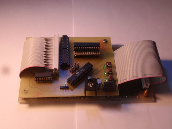
Some other features that we included on the driver board were 3 green LEDs, 3 push buttons, ISP header, TTL header. When all was said and done we ended up the the schematic shown below.
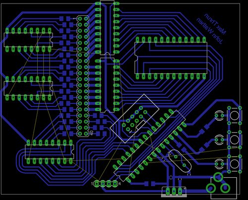
I know, you are probably looking at that and thinking, “Why are all the shift register outputs criss-crossed??”. The reason for doing this is because the output pins on the chip are not exactly in a row so to assist in board layout the pins had to be crossed and mixed up so that the board layout would be nice. It’s much easier to change the order of the columns in the program then it is on the board layout (in my opinion). We didn’t want to etch a double sided board so a lot of effort went into laying as much of the circuit out on a single side. There were a few paths that could not be routed and were just jumped with wire (you’ll see in picture below).
Notice how there are a bunch of air-wires (yellow lines) that I couldn’t figure out how to route, they are manually jumped when the board is put together.
To etch the board we printed out the board layout 1:1 scale on glossy photo paper, it was than ironed onto a piece of copper clad. The idea is that the toner will stick to the copper clad and when the board is dipped in acid the acid will eat away at everything but the traces, since they are coved by the toner. I’m definitely not an expert in this area so ask John Wathen more about the process, he is basically a pro.
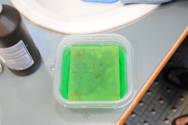
Etching the board in acid

Checking to see if its ready to be scrubbed
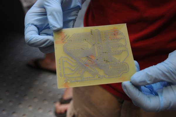
Dirty traces

Scrubbing off the rest of the toner
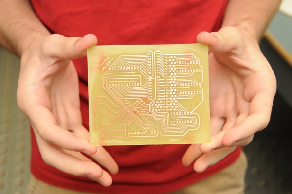
The beautiful result, nice and shiny
Now, let me just tell you that we did this in a public bathroom at school. So there were three guys in a bathroom with latex gloves, a camera, and tub of some green liquid. Trust me we got some weird looks.
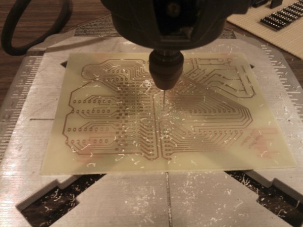
The next step was to drill all the holes. I don’t remember exactly how many there were (John might) but there were a lot.
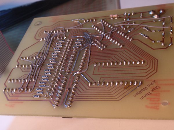
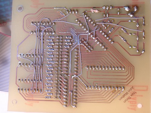
After all the holes were drilled John soldered it all up.
And the result!
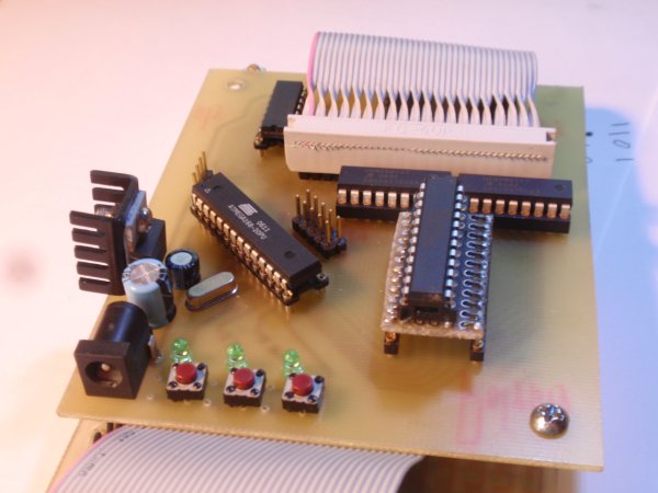
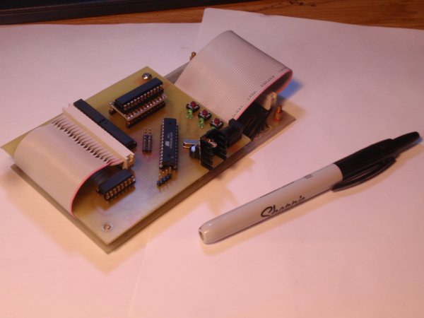
Now that the board was finished it was the moment of truth.
Adam Steele lent me his programmer. Plugged it into my Xbuntu box, apt-get installed the avr tool-kit and the programmer was immediately recognized (NICE!). Flashed a simple program to flash the status LEDs and low and behold, IT WORKED! Next up, everything else. I started by modifying the program that the Intructables provided but quickly got frustrated by the way it worked. It treated each column as a bit in a byte and the rows as a byte, this made it extremely hard to visualize outputs to the display. Also I was using a de-mux and had 24 columns which the code did not easy support. So what do you do in this situation? REWRITE.
An outline of how the new code works:
The value for each pixel is stored in a 2D array 16×24, want to set the top left pixel? buffer[0][0] = 1; simple as that, much easier than dealing with it as an array of bytes. Okay, so it takes up more memory but IMO it is completely worth every bit (pun intended).
The code starts by initializing the ports (pull-ups, in/out, etc) then it initializes timer1. To be completely honest the fill value for the timer was chosen by adjusting value, flashing, seeing if the refresh rate was noticeable. We ended up with OCR1A = 0x012C; as a good value.
The code then falls into an While(1) where it sequentially calls functions to draw stuff on the screen, for example:
Spiral(5, 0);
Tunnel(1);
Tunnel(0);
Tunnel(1);
Erase_Rider(RIGHT, 10);
Fill(LEFT, 10);
Shift(UP, 16, 50);
Erase_Rider(DOWN, 10);
Er
All the high level functions (tunnel, spiral, shift, etc..) write to ‘buffer’. When the timer interrupt goes off it calls the function shift_int() which reorders the columns into ‘buffer_2’ and then shifts them out to the shift registers. It then calls shift_mux() which jumps to the next row. So essentially we have a double buffered display.
Once all the low level code was done it was all fun and games. It was really nice being at the point were all you had to work with is a 2D array. We ended up with the high level functions:
void Delay_ms(int cnt)
void Clear_Display(void)
void Fill_Display(void)
void Flash_Display(u8 cycles, u8 speed)
void Col(u8 col, u8 state)
void Row(u8 row, u8 state)
void Fill_Col(u8 col, u8 dir, u8 speed, u8 state)
void Fill_Row(u8 row, u8 dir, u8 speed, u8 state)
void Fill(u8 dir, u8 speed)
void Invert_Col(u8 col)
void Invert_Row(u8 row)
void Invert_Fill(u8 dir, u8 speed)
void Erase_Rider(u8 dir, u8 speed)
void Spiral(u8 speed, u8 state)
void Tunnel(u8 state)
void Invert(u8 count, u8 speed)
void Draw_Line(u8 x1, u8 y1, u8 x2, u8 y2, u8 state)
void Shift(u8 dir, u8 amount, u8 speed)
void Scroll_Char (char myChar, u8 pos, u8 dir, u8 speed)
void Box(u8 speed, u8 dir, u8 state)
void Grid(u8 speed, u8 state)
It is so incredibly easy to make new functions when you are just manipulating a 2D array.
A warning before you watch the videos, they were taken with a crappy point n shoot camera so they look incredibly choppy. In real life the display is incredibly fluid and smooth. The videos do it zero justice.
Source: http://bear24rw.blogspot.com alternative link: led-animation-circuit-atmega168.RAR

