An interesting project and already much discussed in the forums and also in videos.
Although it appears complex,it is a simple idea and fun very purpose.
Mounting material:
– 27 LEDs matte
– Microprocessor ATmega8
– Electrolytic capacitor 47UF 16V
– Veroboard
– Small wood board at the minimum 10x10cm
– 50 cm wire tinned
(excuse me, I’m portuguese and my english is not very famous :p)
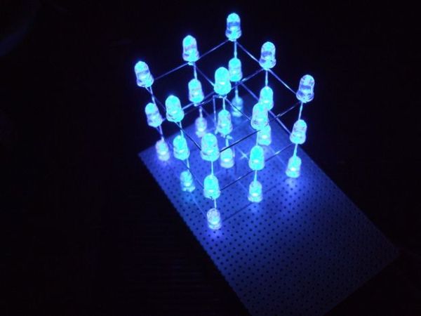
Step 1: Theory of operation of the array of LEDs
The array of LEDs is comprised of 3×9, where three levels are horizontal, and 9 are the vertical rows.
Each LED is turned on a level with a common cathode and each vertical line is connected with a common anode.
So if we want to illuminate a particular LED, just put the level of the 0V line and gave a positive voltage.
To be able to generate an effect of several LEDs on, they have to be powered by multiplexing, a relatively high speed does not seem to be blinking and have a softer light.
As the ATmega8 supports connection of LEDs directly to its pins with a good current, there is no need to put limitation resistors or transistors driver.
Step 2: Creating horizontal levels of the LEDs (negative)
Here becomes more complicated as the presentation of the outcome depends on the linearity on which the LEDs are soldered.
To make it to nine holes with a diameter of 5mm, a board 2cm intervals, where the LEDs can be confident, to be soldiers and bend the terminals in a specific way.
Cathode (negative):
After the LEDs are fixed on board, can be double the cathodes in order to get all nine together, taking care not to bend the center. As the terminals of the LEDs are not sufficient to make the 12 connections, you can use one wire tinned in order to be more esthetic final result.
Anode (positive):
In relation to the anode, must all be folded the same way, so that when you turn the LEDs below it easier to make its welding. Then each anode of the LED, is bent out of its center, and then bent upward at the end of this limit.
These processes are performed for the three horizontal levels in the same way, removing the cathode from the center that will connect directly to Veroboard, creating the negative phase of this level.
Step 3: Creating the vertical rows of LEDs (positive)
Now the three horizontal levels must be attached from the vertical rows, which are the anodes.
In this case the level of the top is attached to the board where they made the holes.
Weld in the center of the cathode terminal, an enameled wire so that it is long to reach Veroboard.
The following relates to grasp the 2nd level which is fixed to the board, solder to all the anodes of the LEDs that were upright, overlapping about 10mm between these two levels.
After being welded, as can also weld the central cathode in order to reach the Veroboard.
With the lower level, the process is similar to the 2nd level
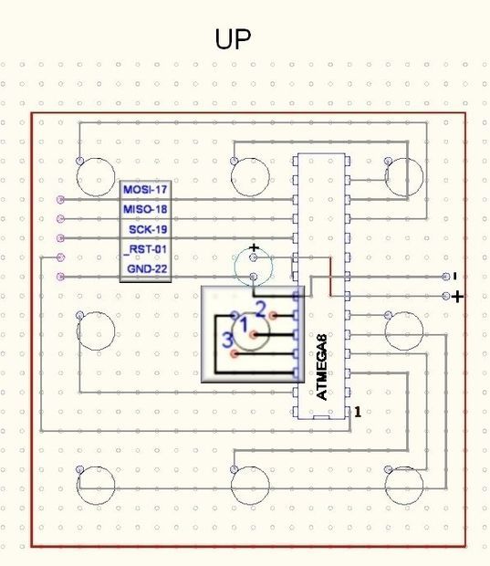
Here we have the hub already fitted and can follow links in the construction of Veroboard.
For more detail: LED Cube 3x3x3 with ATMEGA8