Summary of Line-following car Using atmega32
This project describes a battery-powered line-following toy car that uses three photosensors and an Atmel Mega32 microcontroller to detect paths and turns. The car employs a full H-bridge for front steering and a half-bridge for rear drive motors, utilizing BJTs (TIP102/TIP107) and opto-isolators for control. Originally designed with six to eight sensors, the team settled on three due to space constraints, which necessitated slowing the vehicle's speed via PWM to ensure accurate turn detection.
Parts used in the Line-Following Car:
- TIP107 PNP BJT
- TIP102 NPN BJT
- PS2501-4A Opto-isolator
- QRB1114 Phototransistor
- Mega32 Microcontroller
- MAX232 Multichannel Driver
- Sockets
- Custom PC Board
- Small Solder Board
- Solder Board
- 9V Battery
- Bass Wood Stick
- Poster Boards
- RC Car
- Paint
Introduction
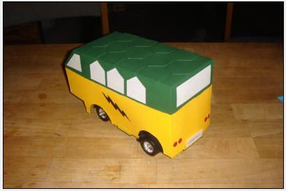
Our project is a battery-powered toy car that is able to follow a path against a background of contrasting color.
<>
The front of the car is fitted with an array of three photosensors, which allows the car to detect the path as well as any turns in the path. Colors that reflect light, such as white, produces a high voltage output from the sensors whereas colors that absorb would output low. By reading the outputs from each of the three sensors, the Atmel Mega32 MCU is able to discern the orientation of the car and whether it is over a straight path or over a turn. The MCU then sends the appropriate logic signals to activate the transistors driving the car’s motors. We use a four-transistor H-bridge circuit to power the front steering motor and a two-transistor half-bridge circuit to run the rear power motors. The H-bridge is able to turn the steering left or right and brake, depending on what logic signal the MCU sends. The half-bridge only drives the rear motor forward and is turned on or off by the MCU.
</>
High Level Design
<>
Rationale and Sources of the Project Idea
Our project was inspired by robot kits that can be purchased to build line-following robot cars. Often, these kits cost well over $100 and we planned on making one that would cost less than $50. Also, typical line-following robot cars move quite slowly and are solely controlled by the car’s rear motors. We wanted our line-following car to move quickly and to use its front wheels as the turning wheels and its rear wheels solely for driving. A line-following car can also be used in a much larger scale to move hazardous or other materials inside factories or storage houses by following designated paths.
Logical Design
A block diagram of high level design is shown below. The three photosensors communicate to the microcontroller via Ports A.0 – A.2. The half H-Bridge, which controls the rear drive motor, is controlled by Port B.3, the PWM output port. The full H-Bridge, which controls the front turning motor, is controlled by the microcontroller through Ports A.3 – A.6. The PC Board that contains the microcontroller is powered using a single 9V battery. Two separate 9V batteries are connected in parallel to power the motors.
Hardware Tradeoffs
Due to spacing constraints, we were not able to mount more photosensors than we had previously anticipated. Originally, we planned to have an array of six to eight sensors across the front of the car. More sensors would enable us to detect how sharp of a turn is ahead with various sensor readings. Instead, we could only fit three sensors comfortably on the front of our car and this fortunately was enough to perform the sensing.
Software Tradeoffs
We wanted to sample the sensor readings as fast as possible so that the car will not miss any turns when it is driving fast. However, since we have three sensors and only one analog to digital converter, we had to take turns sampling each sensor and converting it. However, the MCU requires a certain number of cycles to pass before starting each new conversion. Thus we were forced to slow down the speed at which we sample the ADC. Once we slowed down the ADC readings, our car had difficulty sensing turns because it was driving too fast for the sensors to respond. Therefore, we had to slow our car down as well. Originally, in drive mode, the rear motor was constantly on. To slow the car down, we sent a PWM signal to constantly turn the motor on and off. The PWM slowed the car down to approximately half the original speed. Driving slower, the sensors were then able to sense turns in the track.
Relationship of your design to available IEEE, ISO, ANSI, DIN, and other standards
All components used for our project has been approved by the IEEE compliance standards and there are no standards that pertain to our project.
Existing patents, copyrights, and trademarks which are relevant
There are no relevant copyrights, patents, and trademarks for our project. Line-following robots already exist without a patent and our car implementation does not infringe upon any copyright or trademark.
Hardware
<>
H-Bridge Circuit
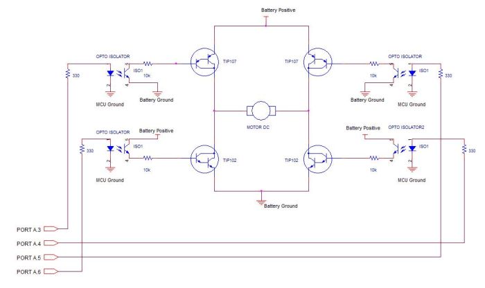
We implemented a full H-Bridge and a half H-Bridge to control the turning of our motors. Since we needed our front motor to turn both directions for left and right, we connected a full H-Bridge to the front motor, which allows us to run the current in two different directions. Because we did not need our car to drive in reverse, a half H-Bridge was sufficient to control the rear motor. A schematic of our full and half H-Bridges are shown in figures 2 and 3 respectively.
The H-Bridge design is essentially four switches, where the switch is a BJT. When the top left and bottom right switches are turned on by a logic high from the MCU, the current will flow from the battery source through the switches and will spin the motor in one direction. When the top right and bottom left switches are turned on, the current will flow the opposite direction through the motor. This opposite direction of current flow causes the motor to spin the opposite direction. When the two top switches are turned on and the bottom two switches are turned off, it creates a short circuit across the motor. This short causes the motor to spin in both directions and hence simulates braking or deceleration. Although we could also stop the car by simply turning off all the transistors, we noticed during testing that there would be a delay when the steering motor turns off. Since we didn’t want the car turning more than it should, we added the braking logic so that there would be quicker stop in the front motor. Switches on the same side (left or right) are never turned. If they are turned on simultaneously, there will be a short circuit across the power supply and will damage the circuitry as well as the power source.
Since the motor will be switching on and off in two directions, protection diodes are needed across the collectors and emitters of the BJTs to prevent inductive kickback that could damage the motor and transistors. Fortunately, the TIP102s and TIP107s we chose already had protection diodes built-in so there was no need for external protection diodes. To ensure that the noise generated by the motor does not affect the MCU power and ground, we used opto-isolators to turn on the BJTs. Ports A3 – A6 are connected to the inputs of the opto-isolators, which isolate MCU power and ground from the H-Bridge power and ground. To prevent too much current flowing from the MCU ports into the input of the opto-isolators, 330Ω resistors were connected to them to limit the current. We chose an opto-isolator packaged with four units on a single chip to facilitate circuit population. Each of the four opto-isolators for the full H-Bridge is connected to the base of one of the four BJTs. Figure 2 shows which MCU ports are connected to which BJT gate.
The half H-Bridge was constructed much the same way except it only used one NPN, one PNP, and two opto-isolators. Only one control signal is required to turn both BJTs on and thus turn the motor on. We did not implement braking for the rear motor because there was no need for sudden braking. The input signal to the BJTs for the rear motor is connected to Port B.3 on the MCU.
H-Bridge Testing and Results
Initially, we tried using NMOS transistors to construct our H-Bridge. In the MOSFET H-Bridge design, the drains of the top two transistors were connected to the positive end of the battery and sources of the bottom two transistors were connected to the negative end of the battery. The sources of the top transistors were connected to the drains of the bottom transistors and the motor was placed between these two nodes. We applied 5V to the gates of the top left and bottom right transistors to supply voltage to the motor. However, the across the motor was consistently around 1V no matter how much voltage we supplied to the H-Bridge. We had first supplied 5V to the H-Bridge with only 1V across the motor. We increased the voltage to the H-Bridge to 12V and the we still measured 1V. We then realized that 5V was insufficient to put the switching NMOS into saturation. Instead, the NMOS transistors were still in the linear region and thus limited the current flow and thus limited the output voltage. We raised the input voltage to the NMOS gates to 7V with a 5V supply to the H-Bridge. This time, the NMOS transistors were in saturation and the H-Bridge gave an output voltage of 4.6V. Although we had gotten our MOSFET H-Bridge to work, the 7V needed to turn on the transistors posed a problem since the MCU ports could only provide 5V when turned high. Also, when we applied 7V to the MOSFETs, they became very hot and this would pose an unacceptable risk to the user. Of course we could use heat sinks but that would increase costs and make construction more inconvenient.
Due to this problem, we decided to try using BJTs instead of MOSFETs for our switching transistors. The two high side transistors were PNPs and the two low side transistors were NPNs. We picked TIP102s for the NPNs and TIP107s for the PNPs because they were both Darlington configurations, which have high current gains, and they had protection diodes built-in. Furthermore, these BJTs came in TO-220 packages which are easy to use on the protoboard. The 10kΩ resistor between the output of the opto-isolator and the base of the BJT limits the current that goes to the gate. According to the TIP102 datasheet, the max base current is 1 A but we decided to be more cautious and use a large resistance value.
We tested the BJT H-Bridge by applying 5V to the top left and bottom right opto-isolators and also supplying a separate 5V to the H-Bridge power supply. This time, the voltage across the motor was approximately 4.6V so we were able to see at least what we were supplying to the H-Bridge across the motor. We then connected the H-Bridge to the motor, and the H-Bridge successfully powered the motor. Since we wanted our car to run without being connected to a power supply, we decided to power the H-Bridges using batteries. We initially thought of using four AA batteries in series to provide 6V to the H-Bridges. However, when we tested the car by supplying 6V to the H-Bridges using the power supply, the car had difficulty fully activating the turning and driving at the same time. The two motors needed at least 7V for them to run simultaneously without problems. Therefore, we decided to power the H-Bridges using a 9V battery. We initially tested running our car off of one 9V battery but the car had difficulty driving because the battery was not providing enough current. Thus, we connected a second 9V battery in parallel to supply the H-Bridge with more current. With increased current, the car ran normally.
Parts List:
| Component | Part Number | Cost/Unit | Quantity | Total Cost |
| PNP BJT | TIP107 | $0.72 | 3 | $2.16 |
| NPN BJT | TIP102 | $0.68 | 3 | $2.04 |
| Opto-isolator | PS2501-4A | $1.95 | 2 | $3.90 |
| Phototransistor | QRB1114 | $1.05 | 3 | $4.15 |
| Microcontroller | Mega32 | $8.00 | 1 | $8.00 |
| Multichannel Driver | MAX232 | Free | 1 | $0.00 |
| Sockets | —– | $0.50 | 4 | $2.00 |
| Custom PC Board | —– | $5.00 | 1 | $5.00 |
| Small Solder Board | —– | $1.00 | 1 | $1.00 |
| Solder Board | —– | $2.50 | 1 | $2.50 |
| 9V Battery | —– | $2.00 | 3 | $6.00 |
| Bass Wood Stick | —– | $0.40 | 2 | $0.80 |
| Poster Boards | —– | $1.00 | 5 | $5.00 |
| RC Car | —– | Free | 1 | $0.00 |
| Paint | —– | Free | 1 | $0.00 |
| TOTAL | $42.55 |
For more detail: Line-following car Using atmega32
- How does the car detect the path?
The car uses an array of three photosensors where white colors produce high voltage output and absorbing colors produce low output. - What type of bridge circuits are used to power the motors?
A four-transistor H-bridge powers the front steering motor, while a two-transistor half-bridge runs the rear power motors. - Why did the designers switch from MOSFETs to BJTs?
MOSFETs required 7V to saturate, exceeding the MCU's 5V output, caused excessive heat, and limited current flow effectively. - Can the car drive in reverse?
No, the rear half-bridge only drives the motor forward, and no braking logic was implemented for the rear motor. - How was the car's speed controlled?
The speed was reduced by sending a PWM signal to constantly turn the rear motor on and off, slowing it to approximately half the original speed. - What components were used to isolate the MCU from motor noise?
Opto-isolators were used to turn on the BJTs, isolating the MCU power and ground from the H-Bridge power and ground. - Why were only three sensors used instead of six or eight?
Spacing constraints on the front of the car prevented mounting more than three sensors comfortably. - How many batteries are needed to power the system?
The system uses one 9V battery for the microcontroller and two separate 9V batteries connected in parallel for the motors.