Summary of Linkit ONE: Flame Sensor
This article outlines a project to detect fire using a flame sensor connected to a Mediatek Linkit ONE board. When the sensor detects a flame, it triggers a buzzer to alert the user. The guide details connecting a lithium battery, wiring the components via a breadboard and jumper wires, uploading specific code, and testing the setup with a matchstick.
Parts used in the Flame Sensor Project:
- Linkit one
- Flame sensor module
- Buzzer module
- Lithium Battery
- Jumper Wires
- Breadboard
This instructable will guide you to use a flame sensor with the Mediatek Linkit ONE. A flame sensor is a device that can detect the presence of fire nearby.

A buzzer connected to linkit one beeps when fire is detected by the sensor.
So let’s get started…… ☺☺?
Step 1: Parts Required
The following parts are required for making this project:
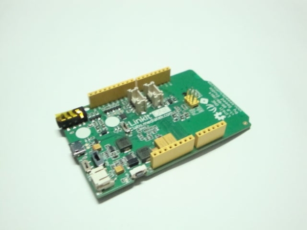
• Linkit one
• Flame sensor module
• Buzzer module
• Lithium Battery
• Jumper Wires
• Breadboard
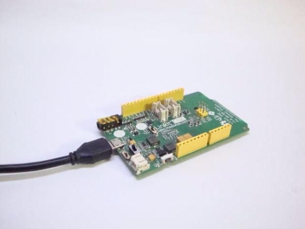
Step 2: Connect the Battery
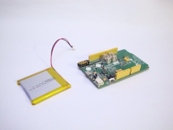
The first or the very basic step is to connect the lithuim ion battery provided with the linkit one to the board. Do so by directly connecting it to it’s respective socket.
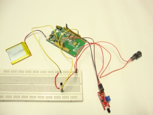
Step 3: Connect the Buzzer
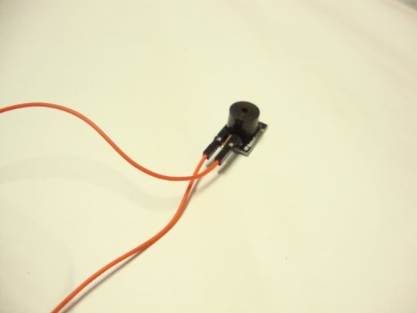
Next step is to connect a buzzer which will beep and give you an alert of fire nearby. It can be connected either directly to linkit one which will not be too loud or through a transistor which will be comparatively louder.
For connecting it, you can refer the image given above. The digital pin that I used was pin no. 2 which is connected to the base of the transistor.
Step 4: Connect the Flame Sensor
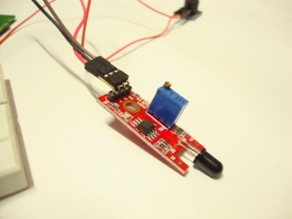
Now you have to connect the flame sensor. It can detect flames through a photodiode present in the front. Connect it as per the follwowing:
• Vcc ————- 5v linkit
• Gnd ————- Gnd
• D0 ————- A0
Step 5: Upload Code
Now the last step is to upload the code to linkit one. You should make sure that the switches are in SPI, USB, UART positions respectively.
\\
void setup()
{
pinMode(2, OUTPUT);
}
void loop()
{
if(analogRead(A0) > 600)
{
digitalWrite(2, HIGH);
}
else
digitalWrite(2, LOW);
delay(100);
}
\\
Step 6: Test
After uploading the code, test the device by first switching it to battery mode and then bringing a lighted matchstick near the sensor. The buzzer would now beep indicating the presence of flame near the sensor.
That brings this instructable to an end. Thanks for watcing!!
Source: Linkit ONE: Flame Sensor
- How does the device alert users to fire?
A buzzer connected to the Linkit One beeps when the flame sensor detects fire nearby. - Can I connect the buzzer directly without a transistor?
Yes, you can connect the buzzer directly to the Linkit One, though it will not be as loud as using a transistor. - Which digital pin is used for the buzzer connection?
The tutorial uses digital pin no. 2, which is connected to the base of the transistor. - What are the correct connections for the flame sensor pins?
Vcc connects to 5v, Gnd connects to Gnd, and D0 connects to A0 on the Linkit One. - What switch positions are required before uploading code?
The switches must be set to SPI, USB, and UART positions respectively. - What analog value triggers the alarm in the code?
The code sets the output to HIGH if the analog read from A0 is greater than 600. - How do you test the completed device?
Switch the device to battery mode and bring a lighted matchstick near the sensor to see if the buzzer beeps.