Introduction
project soundbyte
For our ECE 4760 final project we developed a wireless receiver capable of receiving and playing audio transmitted over an 802.11 Wi-Fi network. Our system was constructed using an Atmel ATxmega256A3U microcontroller and a RN-XV Wifly module made by Roving Networks. We send music to the microcontroller from a computer program running a custom streaming algorithm that incorporates feedback from the microcontroller. When the data is received by the microcontroller it is interpreted and output as an audio to a 3.5mm TRS female connector that can drive any line-in connection. Our streaming system was capable of playing 8-bit mono songs at 44.1kHz or 8-bit stereo at 22.05kHz.
Our original motivation for choosing this project was to create a receiver that could work with Apple Airplay (a proprietary protocol used by Apple to stream data from iTunes, iPhones, etc. to supported speakers). Though we were not able to create a receiver capable of streaming audio over Apple Airplay due to the incapability of available hardware Wi-Fi interfaces, we were able to create our own music streaming system. Additionally, our current system creates a strong basis off of which to work if we do decide to eventually tackle Apple Airplay for a more advanced class (or on our own!). Lastly, streaming music is just a really cool thing to do and is very useful and fun. We really wanted to develop a project that would have some practical use and not just an impressive
High Level Design
As previously mentioned, our rationale for designing a music streaming system was to integrate with Apple Airplay devices. We wanted to create a way of playing music from speakers that were not directly connected to a computer or music playing device. Wi-Fi was chosen as our protocol of choice because (in addition to being what Apple Airplay uses) 802.11 connectivity is especially pervasive and infrastructure networks (like RedRover) allow data transfer over long ranges. The 802.11 Wi-Fi standard is an IEEE LAN/MAN standard for implementing wireless communication at 2.4, 3.6 and 5 GHz frequency bands. For our project we operated at 2.4GHz over a personal ad hoc network and over the RedRover (unsecure) open network.
We designed the structure of our streaming system to be rather simple which would be desired in a commercial product. We constructed the receiver on a single breadboard containing the microcontroller, Wifly, powerplug, audio filters and headphone jack. We send audio data to this receiver using a C++ program written to receive and send UDP packets. In this script we added functionality so that the user could easily select the desired song and pause and play the song at anytime using keyboard shortcuts.
We wanted to play audio at the highest quality possible, so we decided to play it at a 44.1 kHz sampling rate, the standard CD quality sampling rate. Because of this high data rate constraint, timing became the most important part of our design in order to stream music correctly. To play samples at a rate of 44.1 kHz we had to set the clock speed to be a multiple of 44,100. The ATxmega256A3U allowed us to set a custom clock frequency between 33 MHz and 55 MHz in steps of 1024 Hz using the on-board Digital Frequency Locked-Loop (DFLL). Using the DFLL we set the clock speed for the microcontroller at 33,868,800 Hz so that if we played a sample every 768 clock ticks, we would play audio at a rate of 44.1kHz. Therefore, we set a timer period to 768 clock cycles and we had the timer overflow interrupt trigger the DAC conversion. This way every 768 clock cycles the DAC would convert and output an audio sample.
Because of this high data rate, we use a large number of hardware features of the xmega microcontroller to speed program execution. The weakest link in the system is data transfer from the Wifly to the microcontroller. At the highest supported baudrate, 921600 baud, we can theoretically transmit 92,160 bytes/s (8 bits + 1 start and 1 stop bit for every data byte). In reality we found that the maximum data rate was much less than that, for two reasons. First, the Wifly module is designed to use hardware flow control above 115,200 baud. Unable and unwilling to be restricted by this conclusion we attempted to function at the highest supported baud rate (921,600 baud) without hardware flow control. After days of frustration, we discovered that the trick to operating at high baud rates was to insert a 10 microsecond delay between bytes, when transmitting to the Wifly. With this delay in place, the Wifly was able to reliably read transmitted characters without flow control. Without this delay, the Wifly would function erratically, missing bytes that were transmitted.
The second reason we found that reliable data rates were much lower than the theoretical maximum of 92,160 bytes/s was that we experimentally determined that the Wifly began to drop UDP packets before coming close to saturating the 92,160 bytes/s link speed. Due to these limitations we had to limit our streaming to 8-bit mono audio at 44.1kHz or 8 bit stereo audio at 22,050Hz, effectively capping the bitrate on the link to 44,100 bytes/s, less than half the physical maximum.
After data is received by the microcontroller over the Wi-Fi network, it is played by emitting analog samples on the DAC. This analog output is hardware filtered before being sent to the 3.5mm speaker load. To keep down cost and simplify design, we decided not to have a pre-amp to drive our load. This did not seem to be a problem.
As far as we know, our design does not infringe on any trademarks, copyrights, or patents.
Software Design top
Our software consists of firmware for the microcontroller and a PC program that streams audio to the microcontroller. The PC program is currently compatible with 44.1 kHz, single channel wave files, or 8 bit, 22.05 kHz, dual channel wave files. Though the audio data is transmitted to the microcontroller as raw PCM so any music file that can be downsampled to meet either of the above criteria could be played with only minor modifications to the PC program.
Microcontroller Software
Microcontroller software was written and compiled in AVR Studio 5.1. The microcontroller code was derived from a number of low level libraries available as Atmel application notes. Specifically notes AVR1304, AVR1516, AVR1518, AVR1520, and AVR1522 were used. “-O3” optimization was also used.
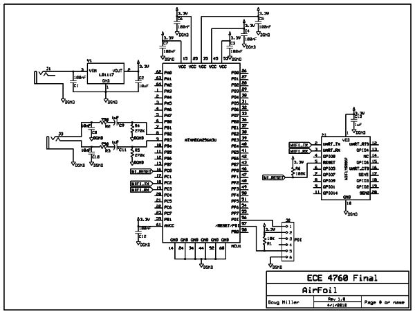
In order to sustain a high rate of data throughput in addition to the exact timing requirements of audio, we used many hardware features of the xmega series. In all, we utilize the USART, both channels of the DAC, three channels of the DMA, two channels of the Event System, and two Timers.
The DMA system was a major pain. We had to do a number of undocumented and unorthodex steps to setup the DMAs to correctly transmit at a relatively continuous rate.
Overview
The system works as follows. Immediately after power on, the clock is switched from the default 2 MHz oscillator to the 32 MHz oscillator. Then the DFLL and the 32kHz internal oscillator are used to trim the 32 MHz oscillator to 33868800 Hz, which is evenly divisible by 1024 Hz (the resolution of the DFLL) and 44.1 kHz, the rate at which music is played.
After clock trimming. The DFLL is disabled and all clocks excepted the 32 MHz clock (now trimmed to 33868800 Hz) are disabled. Input and output ports are then configured and the USART baudrate is set to 9600 baud, the default baudrate of the Wifly. The DAC, timers, Event System, and DMA are initialized along with appropriate buffers. Then Wifly initialization commands are sent which configure to Wifly to join or create a Wi-Fi network and set up the the IP address and port numbers of the remote client that will be streaming music.
After this setup, the baud rate is configured to 921,600 baud and the receiver begins waiting for audio packets.
Initialization and Configuration
The first peripheral to be initialized is the DAC. We initialize both channels of the DAC so that we can play two channel (stereo) audio. In in the initialization of the DAC we enable the optional audio amplifier and enable two timer interrupts. We enable the timer interrupts here because we use one of the timers (Timer C0) to trigger a DMA conversion, and therefore it runs at 44.1kHz (period of 768). The other timer (Timer D0) is used to keep track of milliseconds. We need to keep track of real time for reasons discussed later when discussing audio streaming. After enabling the timers, we setup the DMA for dual channel operation so that the DAC will convert the samples from both channels and play them at the same time. We also set the event control register so that both DAC can be triggered individually.
After setting up the DAC, we initialize the onboard USART. To do this we first set the appropriate pins to output/input in order to setup the TX/RX lines. We then initialize the USART buffers and enable the USART receive interrupt (transmit interrupt is enabled later). Note that we initially receive and transmit data over the USART using interrupts. This is only done in the initial setup of the Wifly. After the Wifly setup is complete we continue to transmit data using USART interrupts but we use the DMA to handle incoming data. The reason for this is that using the DMA to setup the Wifly proved to be very difficult and hard to debug. We also set the microcontroller baud rate to 9600 (the default Wifly baud rate). After USART initialization we enable global interrupts so that we can start receiving and sending data.
Once we can receive and send data we start initializing the Wifly. The Wifly module has its own independent 32-bit processor and onboard TCP/IP stack. This means it is able to do most of the networking calculations on it own as long as it’s configured correctly. To setup the Wifly, string commands must be sent to its UART receive port. This is simple enough but there are many annoying subtleties that can only be discovered through experimentation. These subtleties can be seen later in the Tips/Tricks section for the Wifly. To initialize the Wifly we put the Wifly into command mode and then do a factory reset. This makes sure all previously saved configurations are no longer present and is important when switching between networks. After resetting, we enable the ad hoc network if we are not connecting to another network. We then setup the Wifly to send and receive UDP packets and tell it what port and IP address to send to and listen on. Next we set the communication time which determines how long data the Wifly receives from the microcontroller will stay in the Wifly’s buffer before it is sent out in a UDP packet. The Wifly configuration is then saved and the Wifly is reset so the commands take effect. After the reset, if we are going to join RedRover we do so. The reason we wait to join RedRover is so that the IP address the Wifly gets from the DHCP will be printed out on Putty. Next we send the command to “instantly” set the baud rate of the Wifly to 921,600 baud. The reason we use the “instant” command is so that the baud rate will be changed without another reset and when the Wifly is power cycled it will start back at 9600 baud. After all this, the Wifly is initialized and we disable global interrupts.
The last thing we do before we start streaming is clear the USART buffer. We do this by simply writing all of the data to one element of a trash buffer. This ensures that there is no junk data put into the audio buffer when we begin streaming.
Music Streaming
The system to deliver audio to the DAC is somewhat complicated. So to explain the system, we will work outward to inward, starting from the analog output from the DACs and ending with when it is received by the USART. To output sound to both speakers, we use both channels (channels 0 and 1) of the DAC unit, one for left and one for right. In order to update analog values reliably at 44.1 kHz we used the DAC trigger feature. The DAC can be configured to update its output based on a signal from the Event System. We therefore set Channels 0 and 1 of the DAC to trigger from a signal on the Event System channels 0 and 1, respectively. Channels 0 and 1 of the Event System are triggered when an overflow of Timer C0 occurs, because the system clock is a multiple of 44.1 kHz, Timer C0 can be set to overflow at a rate of exactly 44.1 kHz. So the DAC can be updated at an exact rate of 44.1 kHz with no CPU interaction necessary.
To load values into the DAC data register without CPU intervention, another xmega feature is used, namely the DMA. Two channels of the DMA are setup to transmit blocks of data from a buffer to the DAC data register. The DMA transfers trigger on the DAC data register empty condition, which occurs immediately after the DAC has read in the values in its data register and used them to output a new analog voltage on its DAC output pin. The DMA transfers are configured as single shot. Meaning that they will only send one burst of data (in this case, 1 byte) for every trigger condition received.
After the DMA has completed an entire block transfer (nominally 128 bytes, equivalent to 128 audio samples). It must be periodically reset to load in new data to the DAC. This is accomplished in the Timer C0 overflow interrupt. Because the Timer C0 overflow triggers the DAC update (and consequently the DAC data register empty condition and a subsequent DMA transfer). The Timer C0 overflow interrupt is the perfect place to detect the final DMA transfer and setup the DMA channels for a new block transfer. To do this, a static variable keeps track of the number of overflows that have occurred since the current DMA transfer began. When this number gets to the final transfer, the overflow ISR resets this variable and updates the DMA channels to send a new block.
Audio data for the right and left channels are each kept in their own circular buffer. These audio buffers are large, 4 KB each. The DMA channels that send data to the DAC pull data from these buffers. Data is placed in these audio buffers by the CPU. After initialization, the microcontroller enters a function, Begin_Stream(), in which it stays forever. In this function, the CPU takes data from one of three temporary buffers and places the data into the audio buffers. The data gets into these temporary buffers through yet another channel of the DMA.
Parts List:
| PART | PART NUMBER | VENDER | COST | QUANTITY | TOTAL COST |
|---|---|---|---|---|---|
| — | — | — | — | — | $69.49 |
| 3.5mm Audio Jack | CP1-3523N-ND | Digikey | $0.84 | 1 | $0.84 |
| WiFly RN-XV-W | WRL-10822 | Sparkfun | $34.95 | 1 | $34.95 |
| xbee Breakout Board | BOB-08276 | Sparkfun | $2.95 | 1 | $2.95 |
| 3.3V DC Regulator | 497-1491-5-ND | Digikey | $0.68 | 1 | $0.68 |
| TQFP 64 Breakout | MicrocontrollerShop | DR-SMD2DIP-QFP64 | $4.50 | 1 | $4.50 |
| ATxmega256A3U | ATXMEGA256A3U-AU-ND | Digikey | $9.75 | 1 | $9.75 |
| Capacitors and Resistors | N/A | ECE Lab | Free | N/A | Free |
| Power Barreljack | CP-002A-ND | ECE Lan | $0.92 | 1 | $0.92 |
| AC to DC Power Converter | N/A | ECE Lab | $5.00 | 1 | $5.00 |
| Solder Board | N/A | ECE Lab | $2.50 | 1 | $2.50 |
| Sip Pins | N/A | ECE Lab | $0.05 | 148 | $7.40 |
| Speakers | N/A | Owned | Free | 1 | Free |
For more detail: MAD-DOG Kick-Awesome Wi-Fi Audio Streamer Using Atmega644