Recapitulation
One thing I didn’t find clearly over the internet is how to make an Arduino Pro Mini bare bones, that is, from the scratch, and how to make one on the breadboard. This is really useful if you want to make a custom pcb/smd circuit, because you will be able to test your hardware ans software before sending the schematics and the layout of the board to the manufacturer. Also, it will make your circuit Arduino compatible. If you read my previous article, here, I showed how to make a simple circuit with the PCF8563 real-time clock, reading and writing it. Now it is time to put your Atmega 328p on the breadboard and complete a simple read of the clock, maintaining the power consumption low, and for that I will use the LowPower library.
First steps
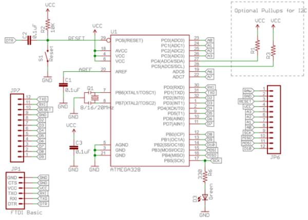
All over the internet there are numerous tutorials about how to make an Arduino Uno bare bones, but it is hard to find a Pro Mini. For our lucky, they are really similar, and a good start can be made by looking for the original Arduino Pro Mini schematic, here. The main circuit is as the next image shows.
From the circuit above, the only part that is not clear are those capacitors on the oscillator pins, one on OSC1 and one on OSC2. For those, I used 22 pF each. The next thing we need to do is to eliminate the voltage regulator from the schematic, because we are going to use this circuit in our smartwatch, and will use a CR2032 or LIR2032, which don’t need them. The voltage regulator and the LED make our power consumption go up a bit, so we can leave them behind.
The red box of the image shows what we don’t want in our breadboard. As for example, we don’t need a LED just to show the Atmega is on, because that would be a terrible waste of precious mA. The green box, however, is very welcome. Watch out not to place the capacitor C13 upside down!
Take a note: watch out that, although this is the schematic for the Arduino Pro Mini, the number of the pin which you will connect each part may vary according to the packet size of the chip you have chosen. To know better about each pin of each packet size you have to check the datasheet.
Placing the RTC
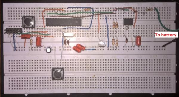
Now, if you read my previous article, you just have to connect A5 to SCL pin on the PCF8563, and the A4 to the SDA pin. Use pull-up resistors on both wires. These resistors can be between 2K and 10K Ohms. In my case I stayed with 2K. The only different pin I used was a button (without any resistors) on the Atmega pin number 4 (or digital input 2), because as we are going to use the power down mode, I want it to wake up via external interrupt.
Read More: How to make an Arduino Pro Mini bare bones with Real-time Clock