Summary of Mastering AVR Microcontrollers: A Hands-On Guide to Project Development
AVR IDE setup and programming guide for ATMEGA168 covering circuit construction, Atmel Studio 7 installation, WINAVR and AVRDUDE integration, USBASP driver setup via Zadig, configuring Atmel Studio to use WINAVR, creating a GCC C project, compiling, setting fuses for external crystal, and programming the chip to blink an LED. It emphasizes using an external 5V regulator, wiring the USBASP 10-to-6 pin adapter for breadboards, and saving the toolchain and programmer settings for reuse.
Parts used in the AVR ATMEGA168 Blinking LED Project:
- ATMEGA168 microcontroller
- USBASP programmer (10-pin to 6-pin adapter)
- 5V regulator 7805
- External crystal (for ATMEGA168 external clock)
- LED
- Current-limiting resistor for LED
- Wires or header leads (to adapt 2.54mm pitch header to breadboard)
- Breadboard, stripboard, veroboard, or PCB (any construction medium)
- Power supply (external 5V source recommended)
- Windows PC with Atmel Studio 7 installed
- WINAVR (with AVRDUDE)
- Zadig driver utility
AVR microcontrollers boast distinct advantages compared to similar microcontrollers, offering higher MIPS and a more user-friendly architecture. This article will delve into mastering the AVR Integrated Development Environment (IDE), guiding readers through the process of creating an executable project. Additionally, it will cover building a fundamental AVR circuit and programming it effectively.
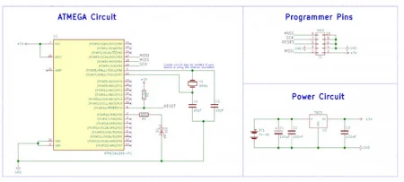
Schematic
How to Build the Circuit
Constructing the circuit proves straightforward and adaptable to various construction techniques like breadboard, stripboard, veroboard, or PCB assembly.
The project schematic illustrates a basic power regulator circuit (utilizing the 7805) to supply the ATMEGA device with 5V. However, note that the USBASP programmer supplies around 3.3V. Despite this, employing an external power source is advisable to prevent the USBASP from potentially drawing excessive current from any USB port.
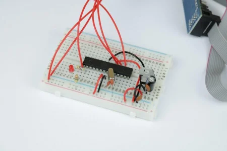
The USBASP programmer I acquired includes a converter to switch the 10-pin program header to a more user-friendly 6-pin format. However, this header, featuring a two-row 2.54mm pitch spacing, isn’t directly compatible with a breadboard. To address this issue, I resolved it by linking the header to wires that reach and connect to the different programming pins on the breadboard.
How to Install AVR Studio
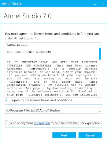
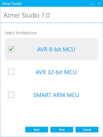
AVR devices are programmed using a customized version of Visual Studio 2015 known as AVR Studio 7, available for download from the AVR website. To initiate the programming process for AVR devices, start by downloading the web installer, a compact application responsible for acquiring the necessary files. After the download completes, proceed to execute the installer.
During the initial installation, you’ll encounter prompts regarding license agreements and the option to send anonymous information. Personally, I advise against sending anonymous data for various reasons (primarily due to extreme caution).
After the download completes, initiate the installer and navigate through the provided options until prompted for an installation destination.
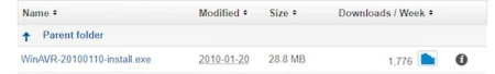
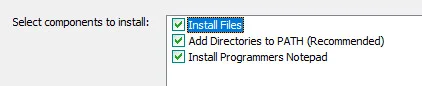
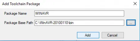
The recommended installation directory for WINAVR is C:\WinAVR-20100110. When prompted for PATH environment options, ensure that all the checkboxes (as illustrated below) are selected.
Once the install button is clicked, the installer will do the rest of the work, and once done, the installer will close.
How to Connect USBASP and Install Driver for Windows
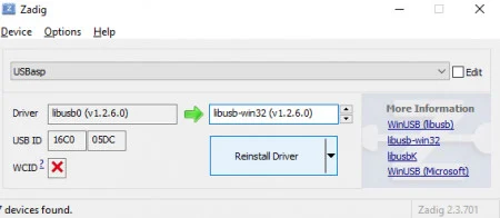
If you’re using Windows, changing the USB driver for the USBASP device can be accomplished effortlessly using a tool called Zadig. Here are the steps: Firstly, download Zadig from the provided link, connect your USBASP device to your PC, and wait for Windows to automatically install USBASP.
Next, launch Zadig, locate the USBASP device from the dropdown menu, and choose the driver labeled “libusb-win32 (v1.2.6.0).” After selecting this driver, click on “Replace Driver” or “Reinstall Driver.”
Zadig will then proceed to automatically install the necessary driver required to enable USBASP functionality on Windows.
How to Configure Atmel Studio 7 and WinAVR

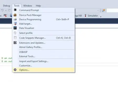
Atmel Studio 7 is now capable of compiling your AVR programs using WINAVR. However, to enable device programming, an external tool must be added and configured for the ATMEGA168 device.
To begin, go to Tools > External tools. This window is essential for configuring the USBASP programmer. Below is a window displaying most of the necessary details that require filling in.
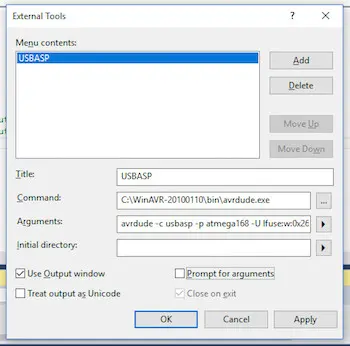
The arguments box doesn’t display all necessary information, so here’s what was input:
avrdude -c usbasp -p atmega168 -U lfuse:w:0x26:m -U flash:w:$(ProjectDir)Debug$(TargetName).hex:i
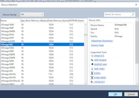
While most of this argument’s details might not concern you, two specific parts are crucial. Firstly, “-p atmega168” signifies to AVRDUDE that the programming is for an ATMEGA168. If your project involves a different chip, replace “atmega168” with your specific device, like “atmega88.”
The second parameter, “-U lfuse:w:0x26:m,” is ATMEGA168-specific. This command configures the device to use an external crystal. Once programmed, the device will only operate when connected to a crystal circuit (refer to the schematic).
Keep in mind that this also means the device necessitates a crystal during programming. Importantly, this argument solely applies to the ATMEGA168! Attempting to use it with other devices may result in damaging those devices (rendering them unusable). To simplify, consider acquiring an ATMEGA168.
Creating Your First Project
The subsequent step is to initiate an AVR project to verify the circuit, compiler, and programmer.
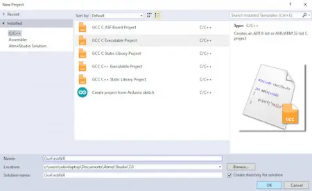
Begin by going to File > New > Project. In the ensuing window, opt for “GCC C Executable Project” and designate a name for the project in the provided text box.
Now, let’s proceed to compile and upload the code to the AVR device.
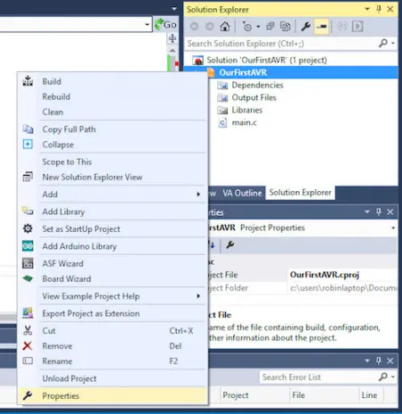
Begin by confirming that our project utilizes the WINAVR compiler. Right-click on the project within the solution window and access the “Advanced” section in the properties window. Within this “Advanced” window, verify that WINAVR is chosen in the Toolchain Flavour box.
Save the project and compile it by clicking Build > Build Solution (or pressing F7).
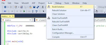
If everything progresses as expected, you should encounter the following message in the output window:
Build succeeded.
========== Build: 1 succeeded or up-to-date, 0 failed, 0 skipped ==========
This indicates that our project has compiled successfully and is now prepared for transfer to our chip.
To program the device, ensure that the USBASP is connected to both the PC and the Atmega circuit, the circuit is powered, and if the IC has been configured to use an external crystal, ensure the chip has a crystal connected.
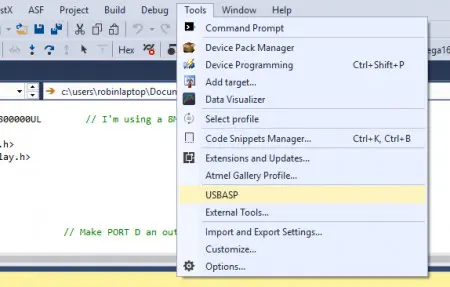
Once these steps are completed, navigate to Tools > USBASP, and from there, the process should proceed automatically.
If everything goes smoothly, the LED on your circuit should begin blinking! Here’s the output from AVRDUDE in Atmel Studio 7, displaying what a successful program execution looks like.
avrdude.exe: warning: cannot set sck period. please check for usbasp firmware update.
avrdude.exe: AVR device initialized and ready to accept instructions
Reading | ################################################## | 100% 0.01s
avrdude.exe: Device signature = 0x1e9406
avrdude.exe: NOTE: FLASH memory has been specified, an erase cycle will be performed
To disable this feature, specify the -D option.
avrdude.exe: erasing chip
avrdude.exe: warning: cannot set sck period. please check for usbasp firmware update.
avrdude.exe: reading input file “0x26”
avrdude.exe: writing lfuse (1 bytes):
Writing | ################################################## | 100% 0.00s
avrdude.exe: 1 bytes of lfuse written
avrdude.exe: verifying lfuse memory against 0x26:
avrdude.exe: load data lfuse data from input file 0x26:
avrdude.exe: input file 0x26 contains 1 bytes
avrdude.exe: reading on-chip lfuse data:
Reading | ################################################## | 100% 0.00s
avrdude.exe: verifying …
avrdude.exe: 1 bytes of lfuse verified
avrdude.exe: reading input file “c:\users\robinlaptop\Documents\Atmel Studio\7.0\OurFirstAVR\OurFirstAVR\Debug\OurFirstAVR.hex”
avrdude.exe: writing flash (184 bytes):
Writing | ################################################## | 100% 0.11s
avrdude.exe: 184 bytes of flash written
avrdude.exe: verifying flash memory against c:\users\robinlaptop\Documents\Atmel Studio\7.0\OurFirstAVR\OurFirstAVR\Debug\OurFirstAVR.hex:
avrdude.exe: load data flash data from input file c:\users\robinlaptop\Documents\Atmel Studio\7.0\OurFirstAVR\OurFirstAVR\Debug\OurFirstAVR.hex:
avrdude.exe: input file c:\users\robinlaptop\Documents\Atmel Studio\7.0\OurFirstAVR\OurFirstAVR\Debug\OurFirstAVR.hex contains 184 bytes
avrdude.exe: reading on-chip flash data:
Reading | ################################################## | 100% 0.10s
avrdude.exe: verifying …
avrdude.exe: 184 bytes of flash verified
avrdude.exe: safemode: Fuses OK
avrdude.exe done. Thank you.
Conclusion
Commencing with AVR devices might pose challenges, particularly if an official programmer isn’t readily compatible with Atmel Studio 7. Nevertheless, setting up just one command line within the programming tool—defining the device type, fuse settings, etc.—allows all subsequent projects to utilize the same tool and compiler, needing configuration only once.
Therefore, the upcoming ATMEGA168 project can employ the same compiler and external tool demonstrated in this project without necessitating alterations. Naturally, more complex projects might require modifications to fuse bits. However, this tutorial should serve as a starting point to initiate your journey with AVR devices.
- What power supply is recommended for the ATMEGA168 circuit?
An external 5V source via a 7805 regulator is recommended because USBASP supplies around 3.3V and external power prevents overloading the USB port. - Can I use the USBASP directly on a breadboard header?
No; the USBASP adapter has a two-row 2.54mm pitch header that is not breadboard friendly, so the article links the header to wires reaching the breadboard pins. - How do I install Atmel Studio 7?
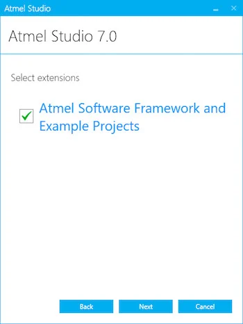
Download the web installer from the AVR website, run it, accept license options, select AVR 8-bit device support and Atmel Software Framework, complete checks, and install then launch Atmel Studio 7. - Why install WINAVR alongside Atmel Studio 7?
Atmel Studio 7 does not natively support AVRDUDE; WINAVR provides AVRDUDE and a GCC toolchain for compiling and uploading code via open-source tools. - How do I install the USBASP driver on Windows?
Use Zadig: connect USBASP, let Windows install it, open Zadig, select USBASP from the list, choose libusb-win32 (v1.2.6.0), and click Replace Driver. - How is WINAVR configured in Atmel Studio 7?
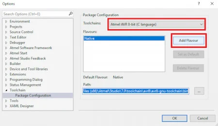
In Tools > Options > Toolchain > Package Configuration, add Atmel AVR 8-bit (C language) flavour pointing to the WINAVR installation directory, then confirm. - How is AVRDUDE set up as an external tool in Atmel Studio 7?
Go to Tools > External tools and add an entry with an AVRDUDE command line, for example avrdude -c usbasp -p atmega168 -U lfuse:w:0x26:m -U flash:w:$(ProjectDir)Debug$(TargetName).hex:i. - Does the lfuse argument apply to other AVR chips?
No; the lfuse value -U lfuse:w:0x26:m is specific to ATMEGA168 for external crystal use and may damage or render other devices unusable. - How do I create and compile the first AVR project?
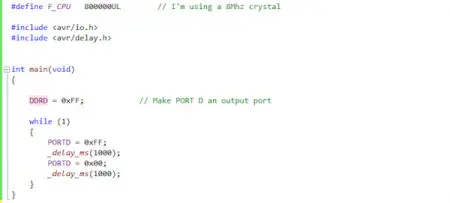
Create File > New > Project, choose GCC C Executable Project, select ATMEGA168, replace main.c with the provided code, ensure WINAVR toolchain flavour is selected, then Build > Build Solution. - How do I program the ATMEGA168 after building?
Power the circuit, ensure USBASP is connected and the crystal is fitted if required, then run the configured Tools > USBASP external tool to invoke AVRDUDE and program the device.