
Summary of Mathematical Manipulation of Pure Sine Wave Inverter Using Atmel 89S2051
This article details a pure sine wave inverter project converting 12V DC to 110V AC at 50 Hz. The approach uses mathematical segmentation of the sine wave to generate pulse trains controlled by an Atmel microcontroller. These pulses drive MOSFETs connected to a transformer, followed by filtering to achieve a clean output with low Total Harmonic Distortion (THD).
Parts used in Pure Sine Wave Inverter:
- Battery providing 12 Volt DC
- Microcontroller 89S2051
- MOSFET power switching circuit
- Transformer
- Filtering components
Introduction
Approach used for creating the pure sine wave described in this paper is done
through manipulation of mathematical representation of the original sine wave. It is
done by dividing half the sine wave into m (even number) segmentations, where
area under a quarter of the sine wave from 0 to π/2 resembles series of the form
[2n-1] where n=1,…, m/2, while areas of the next quarter from π/2 to π will
resemble series of the form [2n-1] where n=m/2,.., 1.
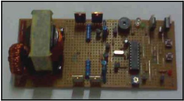
Block Diagram & Schematic
The inverter will converts 12 Volt dc from battery into 110 Volt ac, 50 Hz, sine
wave. Figure 2 and 3 show the block dagram and schemnatic circuit of the inverter.
Pulse train as shown in figures 5 is produced interchangeably from port (A)
and port (B) by microcontroller 89S2051 during the positive half and negative half of
the sine wave. The pulse train is then inputted to the MOSFET power switching
circuit, which is next directed to the primary side of the transformer. Output of the
secondary side is shown in Figure 6, which then be filtered resulting in the sine wave
as seen in figure 7, where amplitude attenuation can reach up to 50%. Measured
inverter output THD reaches 5-8%, where the largest harmonics appeared to be the
second and third harmonics as shown in figure 8.
For more detail: Mathematical Manipulation of Pure Sine Wave Inverter Using Atmel 89S2051
-
How is the pure sine wave created?
It is created by manipulating the mathematical representation of the original sine wave through segmentation. -
What voltage does the inverter convert?
The inverter converts 12 Volt DC from a battery into 110 Volt AC. -
Which microcontroller controls the pulse train?
The microcontroller 89S2051 produces the pulse train interchangeably for positive and negative half cycles. -
Where does the pulse train go after the microcontroller?
The pulse train is inputted to the MOSFET power switching circuit before reaching the transformer primary side. -
Does the output require filtering?
Yes, the output from the transformer secondary side is filtered to result in the final sine wave. -
What is the measured THD of the inverter?
The measured inverter output THD reaches between 5% and 8%. -
Which harmonics appear largest in the output?
The second and third harmonics appeared to be the largest harmonics in the output.
