Summary of Micro:bit Zip Tile Introduction
The article is a step-by-step instructable showing how to connect, configure, and program a Kitronik Zip Tile (8x8 NeoPixel matrix) with a BBC Micro:bit using MakeCode. It covers hardware connections and power considerations, installing the Zip Tile extension, and several progressive example programs (single LED, scrolling text, shifting pixels, row painting) culminating in creating pixel art (a ghost), with links and videos for each program.
Parts used in the Kitronik Zip Tile project:
- BBC Micro:bit
- Kitronik Zip Tile (8x8 NeoPixel matrix)
- 3.5 - 5.3 V power source (example: 3 x AA battery holder with on/off switch)
- Screws (supplied with the Zip Tile)
- Small plastic tubes/spacers (supplied with the Zip Tile)
- Optional: alligator clips (for accessing micro:bit pins)
- Computer with MakeCode editor (for programming)
Before I continue my serie of MU vision sensor instructables for the Micro:bit, I need to make this instructable for the Kitronik Zip Tile, since I am going to use it.
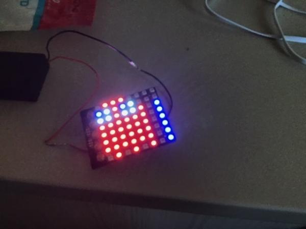
The Kitronik Zip Tile, I will just call it Zip from now on, is an 8×8 neopixel matrix, that can be run fairly easy by the micro:bit. You can actuelly add several Zips together, so you can get a 16×16 neopixel matrix. They are not cheap, but neopixel matrix are never cheap and so I finde the price pretty good.
For this instructable I am going to go through how to set it up and program it. I will go from simple programs to very complex programs.
Supplies:
1 x BBC Micro:bit
3.5 – 5.3 V powersource. I am just using a 3 x AA batery holder with an on/off button
Step 1: Connecting the Micro:bit and the Zip
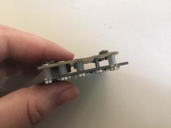
When you bought the zip, it comes with five screws and five small plastic tubes. To connect the micro:bit and zip you simply put the screws into the five big pin holes in the micro:bit, put a small plastic tube on each and then screw them into the zips 5 connectors.
You actuelly only need to connect 3 screws, since the zip only needs data from pin 0. So you only need to connect 3V, GND and pin 0.
You can also choose to not put plastic tubes on all the screws. That will allow you to access the pins, by putting a alligator clip on it. You should always put tubes on at least two of the screws.
Connect the power to the zip and not the micro:bit. The zip needs a lot more power than the micro:bit can provide, but it can power the micro:bit fairly easy. Build in safety measures prevents the zip from being power from the micro:bit.
If you power the micro:bit and zip from two different sources, then these safety meassures will sometimes engage and the zip will stop working. Don’t worry. Just remove all power and wait. After a few minuts it should be working again. This most often happens when you connect the micro:bit to your computer, without removing the power to the zip.
Step 2: Getting the Extension
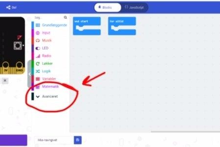
First you go to the Makecode editor and start a new project. You then go to “Advanced” and select “Extensions”. Be aware that since I am danish, these buttons have slightly different names in the pictures. In extensions you search for “zip tile” and select the only result you get.
Step 3: First Program
I am still danish, so my Makecode is in danish, but you can properly still see what the blocks compare to in the english version
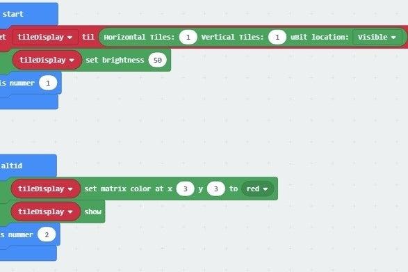
The first block in “On start” (Ved start) initialize the connection betwen the micro:bit and the zip. Here you need to specify how many zips you are using and how they are put together. Since we are only using a single zip we only have a 1×1 matrix, so we set it to 1 vertical and 1 horizontal.
Next block set brightness from 0 to 255. We set it to 50. The zip is very bright. You rarely want to use a brightness over 50.
Then I put in a “Show number” command for trouble shooting. That number will be showed on the micro:bit and not the zip.
In the forever loop the first command sets the LED a 3;3 to turn red. It wont actuelly show the colour, before we call the second command “Show”. That is importent to remember. The set command doesn’t change the colour, before the show command is run.
The code can be found here.
Step 4: Second Program
For the second program we keep the same in “On start”, but change the “forever” loop.
It is actuelly just a single command, that scrolls text over the zip. You can change speed and colour of the text and also add lines under and/or over the text. It is a very useful and easy command
You can find the program here.
Step 5: Program 3
Again we keep the same in “On start”, but change the “forever” loop.
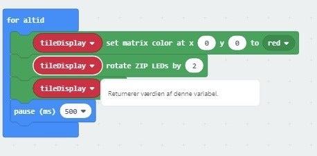
The first command sets the LED at 0;0 to be red. Remember that you can’t see it yet, because we haven’t used the show command.
Imagine that all the LED’s on the zip have a number betwen 1 and 64. Starting with 1 in 0;0, 2 in 0;1 and so on. The second block moves all the LED’s on the zip 2 steps. So 1 become 3 and 2 becomes 4. It repeats, so that 63 becomes 1.
Third block is the show command to show the LED’s that are coloured.
Fourth block just makes the micro:bit wait half a second before it repeats. That way we will quickly have every second LED coloured red.
The program can be found here.
Step 6: Fourth Program
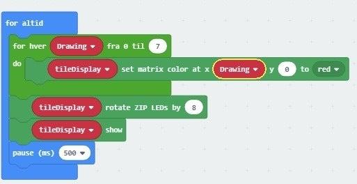
In this program we uses a repeat loop and the “Drawing” variable to paint an entire row red. Then we use the rotate command to the entire row a step and then show it.
The program can be found here.
Step 7: Planing a Bit Art Picture
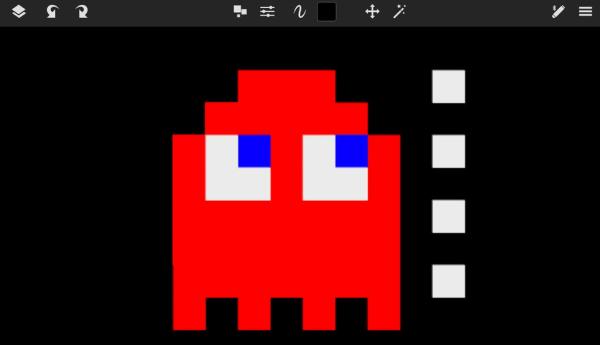
Before the next step I planned what my picture should like like in a drawing program. I drew this pacman like ghost.
Step 8: The Ghost
The first part of the program, marked by a red circle, turns the button 6 LED’s in the first row red.
Then the entire row is moved and the second program part of the program, marked by a blue circle, paints the first row again. First it sets 5 LED’s to red and then it set one of them to white and another to blue.
Again the entire row is moved and a new part of the program paints the thirds row. The program continues like that until the entire ghost have been painted.
It is a long program, so I am not going to upload pictures of all of it. Instead you can find the program here.
Source: Micro:bit Zip Tile Introduction
- How do you physically connect the Micro:bit to the Zip Tile?
Insert the supplied screws through the Micro:bit pin holes, add the small plastic tubes, and screw them into the Zip Tile 5 connectors (only 3 connections—3V, GND, and pin 0—are required). - Can the Zip Tile be powered by the Micro:bit?
No, the Zip Tile needs more power than the Micro:bit can provide; instead power the Zip Tile and let it power the Micro:bit. - What happens if you power the Micro:bit and Zip Tile from two different sources?
Safety measures may engage and the Zip Tile can stop working; removing all power and waiting a few minutes usually restores operation. - How do you add the Zip Tile extension in MakeCode?
In MakeCode start a new project, go to Advanced then Extensions, search for zip tile, and select the extension. - What initial setup is required in the On start block for a single Zip Tile?
Initialize the Zip connection and set the matrix size to 1 vertical and 1 horizontal, then set brightness (author suggests around 50). - Does setting an LED color immediately show it on the Zip Tile?
No, you must call the Show command after setting LEDs for the colors to appear. - What is an easy way to display text on the Zip Tile?
Use the scroll text command in MakeCode which scrolls text, with adjustable speed, color, and optional lines above or below. - How can you create moving pixel effects on the Zip Tile?
Set LEDs, use the move/rotate commands to shift pixels by steps, then use Show and a wait to animate the effect. - What approach did the author use to create pixel art like the ghost?
Plan the image in a drawing program then sequentially paint rows using set, move, and show blocks to build the picture across the matrix.