Summary of Microcontroller Projects: Home Automation System
This article describes a touch-control home automation system using an ATmega8 microcontroller to manage up to six electrical devices. It features real-time monitoring, a dedicated keyboard for settings, and is housed in a portable CPU chassis powered by an ATX supply. The system includes standby modes, power indicators, and relay-based load control.
Parts used in the Home Automation System:
- Atmel ATmega8 microcontroller
- DS1307 RTC chip
- NE555 timer IC
- Relay RL1
- Relay RL2
- LED1 (Power-on indicator)
- LED2 (System-active indicator)
- LED3 (Device-control signal indicator)
- LED4 (Shut-down indicator)
- LED5 (Standby mode indicator)
- Touch-control module
- Keyboard interface module
- CPU chassis of a desktop computer
- 400W ATX power supply
In this era of digital revolution, we are surrounded by smart devices that are capable of making decisions on their own without much human intervention. Our home can also be made smart by implementing a real-time home automation system that monitors parameters like power consumption and human presence. Home automation may include centralised control of electrical devices including lightings, appliances and security.
Presented here is a touch-control based home automation system that can control up to six electrical devices. It also has a separate keyboard interface module for troubleshooting and system settings.
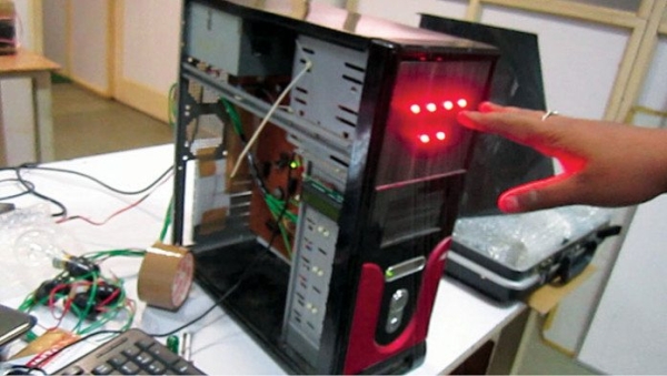
This system consists of closely-networked Atmel’s ATmega8, which is an AVR based microcontroller with 512 bytes EEPROM on a 28-pin DIP package, 1024 bytes internal SRAM and 8kB internal flash memory. The complete system is assembled in a small, portable central processing unit (CPU) chassis for an aesthetic look and uninterrupted 24×7 usage. Author’s prototype is shown in Fig. 1.
Circuit and working
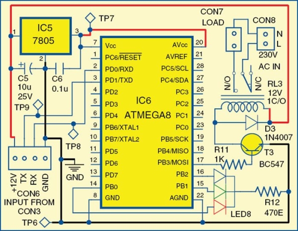
The circuit has four sections: main module, relay module, touch-control module and keyboard interface module. The system is housed on the CPU chassis of a desktop computer and is powered by 400W ATX power supply for error-free operation and proper power delivery to the system.
Advanced Technology eXtended (ATX) is a motherboard form factor specification developed by Intel in 1995 to maintain the integrity and sustainability of the system.
Home automation system: main module
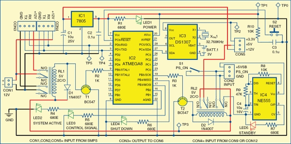
The circuit of the main module is shown in Fig. 2. It has ATmega8 microcontroller, DS1307 RTC chip and NE555 as the main components. The main module controls the load through switching relay RL1.
The system has a standby mode indicator. During standby mode, LED5 glows and power consumption is about 10mW. The ground pin of NE555 timer (IC4) is connected to GND pin of CON2 through relay RL2. LED1 is a power-on indicator and LED2 is a system-active indicator. When RL1 is energised, LED2 glows, indicating that 12V is available from CON1 to CON3 and the complete system is active.
LED3 is a device-control signal indicator that glows momentarily whenever you switch on or switch off a device. LED4 is a shut-down indicator. It glows when a shut-down command is received from the user till the system shuts down completely.
Source: Microcontroller Projects: Home Automation System
- How many electrical devices can this system control?
The system can control up to six electrical devices. - What microcontroller is used in the main module?
The system uses the Atmel ATmega8 microcontroller. - Can the system operate continuously without interruption?
Yes, it is assembled in a portable CPU chassis for uninterrupted 24×7 usage. - What component provides power to the entire system?
A 400W ATX power supply powers the system for error-free operation. - Which LED indicates that the system is active?
LED2 glows when the system is active and 12V is available. - How much power does the system consume during standby mode?
Power consumption is about 10mW during standby mode. - What happens when a shut-down command is received?
LED4 glows when a shut-down command is received until the system shuts down completely. - Does the device-control signal indicator glow continuously?
No, LED3 glows momentarily whenever you switch on or switch off a device.