The Micro Kart 644 is a mobile device that provides additional capability to the traditional RC car experience. Allowable functions are recording multiple tracks, which consist of all user controls sent to the car over a 25 second interval, and replaying the tracks so the cars replicate the movements made during the recording. In addition, we interfaced with not one but two cars, which allows the user to mix the recording and playing of each car and come up with interesting double track replays. Applications of our system include recording a race between two cars and immediate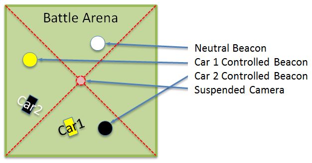 ly replaying the race before your eyes.
Radio controlled cars are a classic toy for children, yet most improvements since its invention over 50 years ago have been mechanical in nature – improving their speed, power, or appearance. These improvements have greatly expanded the available market, as there exist a wide variety of toy-grade or hobby-grade cars, electric, nitro or gas powered cars, and a variety of accessories. We decided that by integrating a microcontroller into the controller of these cars, we would provide the user with even more capability to interface with their car, and overall improve their driving experience. Our first attempt was to create an arena where you could play a beacon-capture game in a battle arena against either an artificial intelligent opponent or your friend. When this proved too time consuming to get the video to work, we spent our remaining time implementing some features that did not require video, such as recording a car’s movements and playing them back.
High Level Design
Overview
For our final project our goal was to create a system to easily control several RC cars through a microcontroller as well as add additional features to the functions of these cars through the use of the microcontroller. In order to accomplish this goal we looked for the simplest way to interface with the RC cars that still allowed us the most control. In addition, the lack of resources on the microcontroller constrained our design to be efficient in terms of memory usage as well as being reasonably low powered to allow the use of a battery as our power supply.
These criteria led our design to be structured into two portions: the interface with the controller, and the interface between software and user. The interface with the RC car controllers is a rather simple one consisting of a direct connection to the power and ground of the controllers as well as to the individual direction buttons. The user interface consists of four buttons and a 2×16 LCD display. The buttons control various settings of the program while the LCD screen displays the present status of the program.
The only standard relevant to our project is the IEEE radio frequency standards. The RC cars are driven at 27MHz and 49MHz, which puts it in the HF (high frequency) band, which is perfectly legal.
Trade-offs
While developing this design several tradeoffs were made between hardware complexity, simplicity of use, and feature-fullness of the final product. The simplicity of the hardware interface with the RC cars was a compromise we made to allow our an easy setup with the controllers, just six solder connections, while still allowing us as much functionality as we thought necessary, i.e. setting the output of the buttons or reading a user’s input at those buttons. Several more complicated schemes were discussed, including ones that would use additional external switches to allow the controllers to be unpowered on command, causing them to not control the cars when users would not be using them, which could be used to save power. Interfaces such as these slightly increase the abilities of our system, but at the cost of drastic increase in complexity that is unwarranted for such small gains.
For the software, the number of features implemented was restricted due to the size and speed of the microcontroller. The program was limited in its memory to only 4kB and as such a large store of tracks for the cars was infeasible. In addition, the rate of sampling had to be taken into account to ensure that replay was smooth, and accurate. Thus the software samples the cars input at a rate of 100 times per second and only store 2 tracks for each car, each lasting approximately 15 seconds. This uses up nearly all of the onboard memory and yet allows for an accurate replay for a reasonable amount of time.
Software Design & Implementation top
Microcontroller
The software for our final project runs exclusively on the microcontroller using the TinyRealTime kernel as the base. It consists of three multi-tasked functions, input, mode, and LCD_update, described below. These functions are all run independently by the kernel with no additional support from the microcontroller. The program starts with a few lines of initialization code after which control is given to the kernel to begin running the main functions of our program.
Input
This function is in charge of reading the state of the buttons, debouncing them and processing them correctly when they are pushed. It used a simple four-state debounce state machine for each of the four buttons, waiting for 20ms between each transition. After debouncing the buttons it checks if any of them have been reset, released, and are currently pushed in which case it performs the corresponding action. The actions are carried out by setting global variables changing the state of the program and signalling the other functions to use the updated values. This function is scheduled to run every 20ms.
LCD_update
This function performs the updates to the LCD based on the global state variables, allowing the user to understand what state the program is in. A compact representation of the state was chosen to fit all the information within the 2×16 character LCD display without the need for changing screens. There is a single large if else block to print the correct characters and values to a buffer for LCD. This is followed by a set of functions that causes only characters that actually changed between the current buffer and the previous buffer to display, which eliminates flashing and significantly speeds up the execution of this function. This function is scheduled every 200ms.
Mode
This is the function that implements most of the functionality associated with the RC cars. It controls the recording and playback of the inputs. During recording mode this function stores the values of the selected car’s controller inputs into an array. This is actually an inverted array because the controllers are active low but the inversion is handled during playback since we have to do some more bit-masking to get the correct data out of the array anyways. As stated when in playback mode the program simply starts at the beginning of the array and places each byte after some bit manipulations onto the pins connected to the controllers. At the end of the array we loop to the beginning allowing interesting repeating patterns to be created. This function is scheduled to run every 10ms to attain maximal accuracy while still keeping the amount of memory needed for the array within the bounds set by the onboard memory of the microcontroller.
Hardware Design & Implementation top
Hardware Overview
The hardware needed by the Micro Kart 644 was mostly already finished (see Early Work) – we needed to solder wires to the controllers’ buttons to allow the microcontroller to control them. In addition, we required an LCD display to be connected to Port C of the microcontroller. This was done by soldering female headers to a second solderboard as well as a ribbon wire to connect to the lower solderboard which contained the microcontroller. We replaced the power supply with a 9V battery, making our project very mobile. Finally, we used pin/header connections whenever we could. so that controllers could be added/removed easily without desoldering connections.
Parts List:
| Category | Item | Vendor | Unit Cost | Quantity | Total Cost |
|---|---|---|---|---|---|
| Electronics | Prototype Board | ECE 4760 Lab | $4.00 | 1 | $4.00 |
| ATMega644 | ECE 4760 Lab | $6.00 | 1 | $6.00 | |
| 9V Battery | ECE 4760 Lab | $2.00 | 1 | $2.00 | |
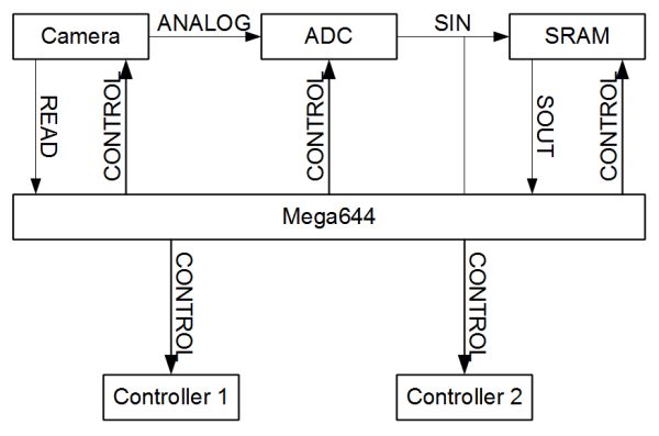
| 1Msps 8-bit ADC AD7478 (Digikey P/N:AD7478ARTZREEL7CT-ND) | Analog Devices | $3.21 | 1 | $3.21 | |
| 20MHz Serial In Serial Out 256k(32×8) SRAM (Digikey P/N:766-1043-ND) | ON Semiconductor | $3.47 | 1 | $3.47 | |
| Mini RC Car | Create Toys | $10.00 | 2 | $20.00 | |
| LCD Display (2×16) | ECE 4760 Lab | $8.00 | 1 | $8.00 | |
| 4 Grouped Push Buttons | ECE 4760 Lab | $0.00 | 1 | $0.00 | |
| 10K Potentiometer | ECE 4760 Lab | $0.00 | 1 | $0.00 | |
| Connections | Solder Board (6 inch) | ECE 4760 Lab | $2.50 | 2 | $5.00 |
| Header Pins | ECE 4760 Lab | $0.05 | 150 | $7.50 | |
| Wire | ECE 4760 Lab | $0.00 | N.A. | $0.00 | |
| Physical Structures | Rubber Feet | ECE 4760 Lab | $0.00 | 1 | $0.00 |
| #4 2-inch Bolts | ECE 4760 Lab | $0.00 | 4 | $0.00 | |
| 1-inch #6 Spacers | ECE 4760 Lab | $0.00 | 8 | $0.00 | |
| #4 Nuts | ECE 4760 Lab | $0.00 | 4 | $0.00 | |
| Total | $55.18 |
For more detail: MicroKart 644