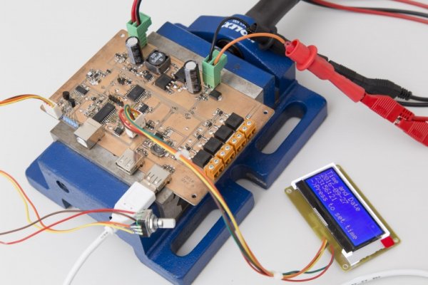
Summary of MPPT solar charger
The article details the prototype development and software implementation of an MPPT solar charger, highlighting successful low standby current achievements and key features. The power supply uses a low-power buck regulator (TPS62120) enabling microcontroller-controlled output voltage switching between 2.2V and 3.3V, achieving standby currents around 13-14µA. The microcontroller, a PIC18F26J50, operates initially at 8MHz and can switch to 48MHz or 32.768kHz clocks to manage real-time clock functions. While software is not finalized and USB functionality is pending, the core design demonstrates effective low power operation with areas identified for improvement.
Parts used in the MPPT Solar Charger:
- Texas Instruments TPS62120 low-power buck regulator
- PIC18F26J50 microcontroller
- 8 MHz primary oscillator crystal
- 32.768 kHz secondary oscillator crystal (for RTCC)
- Voltage divider components (resistors for output voltage setting)
In a previous post I have presented a design for an MPPT Solar Charger. In the mean time I have built a prototype and also wrote some software for it. So today I’ll go through my findings of what works well and what needs to be improved. And yes, there are some flaws in the design…
The software is far from final but with the notable exception of USB all the basic functionality has been implemented.
Power Supply
One of my main goals with this design is to archieve very low standby current, somewhere in the tens of microamps. The basis for this is a low-power buck on the basis of a Texas TPS62120 where the microcontroller can switch the output voltage between 2.2 and 3.3 volts nominally. This works as intended. With no load and the output voltage low, the supply consumes 12.9 microamps at 12V input voltage. With the high output voltage the idle current goes up to 14.3uA. Quite a bit of that current is due to the voltage divider that sets the output voltage. The regulator itself consumes about 9uA in both cases.
Microcontroller
The PIC18F26J50 starts up using the primary oscillator’s 8MHz crystal with the internal PLL disabled. It can then switch to 48MHz operation by enabling the PLL or to the secondary oscillator running at 32.768kHz. The latter is always running since it also serves as the clock source to the real-time clock and calender (RTCC). Switching between clock sources as well as the RTCC have been implemented in software and work fine.
For more detail: MPPT solar charger

