Introduction:
Our project is a two player tilt controlled video game based on the classic Light Cycle arcade game. The purpose of the game is to guide your player through the arena avoiding the boundaries and trails created by you and your opponent. Whichever player causes his or her opponent to crash is victorious.

Our project was divided into three portions: The actual game software, the tilt controllers, and the video generation. The control scheme used accelerometer based controllers to allow the user to turn, speed up, and slow down by tilting the controller. To achieve high resolution color video with a good frame rate, external hardware was used to generate the synchronization timing and RGB TV signal.
The backend software components for the controllers and video generation was broken down into modular componenets. The game software was written specifically to interface with these controller and video generation libraries.
High Level Design:
The goal of our project was to make a game for the color TV that would use novel controllers. The source of the idea for our game is Light Cycle from the movie Tron, and we decided on using accelerometers in our controllers to make it novel. We chose Light Cycle because it is a game that color greatly improves both visually and in gameplay (because it helps differentiate between the two players), and accelerometers are good controllers for it in that they help mimic a pilots controls and a two dimensional accelerometer has all the different inputs that we need to control one player. Our game is based on the arcade game but has two human players, and the Light Cycles are controlled by accelerometers.
The ATMega32 microcontroller runs the game and creates an RGB signal for the AD724. The ELM304 sends a composite sync signal to the AD724 and microcontroller. This syncs the AD724 and microcontroller, and makes it possible for the microcontroller time the RGB signal. The AD724 encodes the RGB signal into a composite video output to send to the color TV.
Design Tradeoffs
Our design involved many software/hardware complexity tradeoffs. These tradeoffs mainly involved the controller design and color TV generation portions of our project. In the controller portion, we needed to decide where to place to ADC input multiplexing mechanism, and in video generation portion, we had to decide where to place the synchronization mechanisms
Standards, Copyrights, and Legal Considerations
This project exports a signal to a color standard television and it must conform to the NTSC television standard. We needed to include a 3.58 MHz sideband for the color TV signal, and also provide the red, green, and blue (RGB) values for this sideband. Our adherence to this standard is discussed in more detail below.
We awknowledge that the rights to Tron are owned by Disney Corporation. Our Light Cycle game is inspired by the Light Cycles subgame of the 1982 arcade video game based on the movie. We are not in violation of any copyrights as our game is only very loosely based on the original arcade classic and is not distributed for profit.
Hardware Design:
The circuit we built for this project is comprised of the ATMega32 microcontroller, ELM304, AD724, and wires leading to the two MMA6261Q accelerometers (partially wrapped in yellow electrical tape).
Video Generation
The color TV signal generation part of the circuit is a modified version of the circuits we studied from previous years’ Color TV projects. Initially, we had three DACs for our RGB inputs to the AD724. There were three bits for red, three bits for green, and two for blue. Later we realized we only need three distinct colors for our game, so one bit for each color is more than enough. We also increased capacitances for the AC-Coupled RGB inputs to get a sharper image on the TV. The crystal oscillator setup for the AD724 gave us poor video quality, so we tried hooking it up to the same crystal we used for the ELM304. This greatly improved our results.
ELM304
The ELM304 is originally intended to be used to generate a solid white raster or a four-level grey scale pattern to provide a stable video input signal for use while recording audio in video cassette recorders, but we use it to generate a composite sync input to the AD724 and let us know which phase of video generation our ATMega32 should be outputting. The outputs from the ELM304 (V1, V2, and V3) change during each signal phase according to the following chart taken from the ELM304 datasheet:
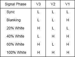
White raster mode is used in our project, so only sync, blanking, and 100% white apply. We hooked the output from V1 to two of our port pins for two interrupts.
- V1 lets us know when the video signal enters and leaves the sync phase (highlighted in blue above). Which kind of pulse the AD724 is outputting, which line to display, and when a new frame should start is kept track of in the interrupt code.
AD724
-
-
-
- The AD724 encodes red, green, and blue color component signals into their corresponding luminance, chrominance, and composite video output signals in accordance with NTSC or PAL standards. We use NTSC since thats the North American TV standard. The microcontroller generates the correct RGB signal and the ELM304 generates the composite sync signal.
-
-
Controllers
MMA6261Q
These diagrams from the MMA6261Q datasheet helps illustrate how this accelerometer works:
In the physical model, when a force is applied to the structure, the center beam moves closer to one of the fixed beams and farther from the other. The change in distance can be used to measure acceleration. The same principle is applied to the equivalent circuit model. When a force is applied, the center plate moves, and each capacitors value will change following the equation C = AT/D (A = area of plate, T = dielectric constant, D = distance between plates).
We used these accelerometers as controllers for our game. They are both hooked up to port A of the microcontroller, and the ADC rotates through polling all of them (it checks player 1s X acceleration, then player 1s Y acceleration, then player2s X acceleration, then player2s Y acceleration). Tilting the accelerometer forwards accelerates, backwards decelerates, left turns left, and right turns right.

The accelerometers we used were already soldered onto boards for us, so we just had to wire them to our ports. The boards are covered in insulating foam and encapsulated in cardboard boxes which are wrapped in electrical tape to ensure the players safety. A hollowed out pen is tape just below the cardboard box to make the controller easier for the player to hold.
For more detail: Multi-Player Light Cycle on Color TV Using Atmega32