Introduction
The purpose of this project was to design a dancing puppet which is musically controlled by the microcontroller. This is a simple, inexpensive dancing puppet, which can dance to any tune you want. For as little money as possible, you can bring Pinocchio to life. Pinocchio can move, twist and dance to whatever tune is being played. With a smart efficient synchronizing system, two motors, and other electrical domains such as analog circuit design, we have created the most imaginable Michael Jackson puppet ever.
High Level Design
Rationale and Sources of Project Idea
This project was inspired from our one of our previous labs: Lab 2, where speech synthesis in the form of DDS was used to generate Cricket Calls according to arbitrary combinations of parameters entered by users. The need of dancing puppets in form of marionettes as toys for little kids was also another incentive. The previous project on the Musical Water Fountain [1], where the water responded to the musical beats was an ideal inspiration. We were interested in building a robot initially but we felt that it might be difficult to obtain the smoothness in the dance moves for the robot. This was mainly due to two reasons. First, the robot had to be imported from the Robotics laboratory, which meant we could not have access to it whenever we wanted and secondly, it was not completely balanced so it could not have leg movements. We had just a few weeks to build and manipulate a robot. Instead we came up with the idea of using a puppet as our object and making it dance to the beats! We found sample marionettes and similar projects from different comedic websites but they were all hand-controlled or beyond the scope of a semester long project. We figured we could make them motor-controlled and eliminate the use of hands controlling puppets to entertain loyal viewers. This was basically an idea to carry out a fun project for everyone i.e. the team members as well as other students and involved software, hardware and mechanical engineering basics.
Dance Moves
The puppet has two dance modes. One is a fast dance move triggered when a strong bass signal is detected. The other move is a slower and more constant move triggered when mid-range frequency signals are detected. Those signals include voice, guitar and piano tunes. The dance moves switches between those two modes automatically and live as the music changes.
Background Math
The background math involves calculating the cut off frequency to sample the sounds at intervals which do not cause any aliasing of the signals. We decided to sample the incoming audio signal at 2kHz frequency which is conveniently located within the audible range of humans. To obtain this we had to compute the cut off frequency which is defined by the Nyquist Theorem which states that the highest frequency that can be accurately represented is given by twice the sampling frequency.
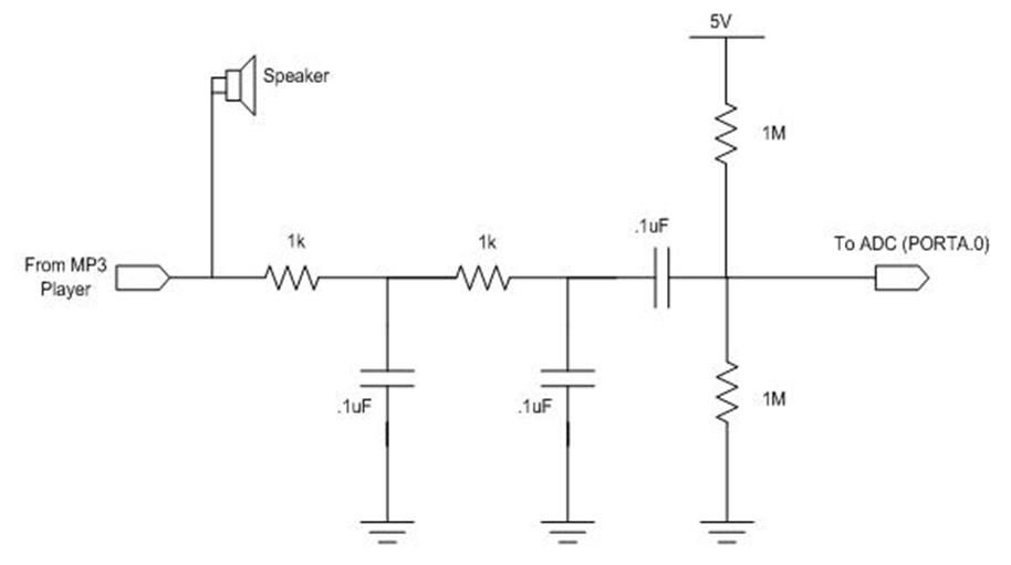
This was followed by implementing the hardware circuitry for the two-pole RC low-pass filters. This involved choosing the RC values such that
R*C = T
where T= Time constant.
Refer to figure 3 for the detailed values of the R’s and C’s that we used.
The cut off frequency of the analog filter is 1Khz
We also implemented a digital low pass filter in software. We found the coefficients in Matlab for the two-pole Butterworth Filter implemented digitally in the program. These were found to be
b(1) = 0.1410 b(2) = 0.2820 b(3) = 0.1410
a(1) = 1.0000 a(2) =-0.6940 a(3) = 0.2580
The Butterworth filter uses the following equation to low-pass filter out the signals.
b(1)*x(n)+b(2)*x(n-1)+b(3)*x(n-2) =
b(1)*x(n)+2*b(1)*x(n-1)+b(1)*x(n-2) =
b(1)* (x(n)+(x(n-1)<<1)+x(n-2))
where x(n) is the input signal at instant n;
x(n-1) is input value at instant n-1;
y(n) is the output value at instant n;
b(n) is the coefficient for the input values and
a(n) the coefficient for the output values.
For further details refer to the Math page [2] by Professor Bruce.
It was also needed to bias the input voltage to the ADC, so as to prevent the ADC from getting negative values and burning out. This was simply carried out using a voltage divider circuit with R values calculated as
I1R1 = I2R2 = Vcc/2 = 2.5V
R1 = R2 = 1M ohm.
Logical Structure
Input Block
Different frequencies as a combination are provided from the musical device such as Ipod, laptop Winamp or an MP3 player as an input to the microcontroller unit, for carrying out mathematical computations like filtering and transformations into the time domain. These frequencies are then low-pass filtered using the RC circuit shown in fig. 3 and also biased to remove any negative voltage to the ADC in the microcontroller unit.
The same music is also fed to the speakers so that it is audible to humans and we can then see the puppet dance to the rhythm we hear.
Microcontroller Unit
The microcontroller unit is used for digitally filtering the signal after converting the analog signal from the device into a digital signal using an 8 bit analog-to-digital converter.
ADC
After the music signal is filtered by the RC low pass filter implemented in hardware, the resulting signal is fed into the ADC of the MCU. The analog to digital converter is set to capture music signals at a rate of 2kHZ. This sampling rate is chosen because the maximum signal that we want to capture is 1kHZ. Musical frequencies higher than that are not very useful for dancing purposes for the puppet.
The Analog to digital conversion is accurately timed using the Timer 0 compare interrupt. That interrupt service routine is set to fire every 0.5ms by setting the OCR0 to 125. The ADC conversion, carried out in ISR also gets executed every 0.5ms and hence samples the music signals at a frequency of 2kHZ. The accuracy and monitoring of the sampling frequency is very important because filters implemented in our project depend on that particular sampling frequency.
The ADC reference is set to the external Aref. Therefore the Aref jumper needs to be connected on the STK500.
Signals entering the ADC on pin A0 of the STK500 are DC offset at 2.5V using a voltage divider. Therefore, the ADC values when no music is played is 127. Since the average amplitude of music signals being supplied is 1V. The ADC values will vary from about 80 to 170.
Output Blocks
The LEDs and Motors are placed at the output end of the system. This converted output from the microcontroller port pins is sent to the 2 LEDs corresponding to 2 motors.
LED5 glows according to the bass of the music played and LED2 is made to glow when strong mid-range frequency signals are detected. The LEDs are being used to confirm the accuracy of the output being fed to the motors.
Further, the 2 motors do receive the same input as the LEDs and are used for driving the limbs of the marionette. The legs are attached to one of the motors and the hands are attached to the other motor.
Finally, the marionette is in sync with the music being played, i.e. its movements follow the bass frequency and other beats continuously. Strings are used to attach to the motor which causes the movement of the limbs.
Our whole project was built on a clamp which can be attached to the side of a table or a smooth edge and two wooden planks were screwed to place the motors on. The motors were placed perpendicularly one above the other. A flat wooden piece was glued to one end of each of the motors. These were in the shape of a cross i.e. perpendicular to each other so that the rotary motion of the motor is converted to the swinging motion of the wooden pieces. Thus, moving the strings which were tied tightly to each end of the flat wooden piece, and to the wooden top of the dancing Pinocchio, which were connected to each pair of limbs.
Hardware/Software Tradeoffs
Filters used
The software tradeoffs included using digital filters instead of the Walsh transform and therefore the sampling of the sound was different as we didnt need the fast speed and sampling rate of the Walsh transform. This was mainly due to the fact that the faster the motor spins the more difficult it is to control the movement of the strings attached as that would be in the order of ms and the motion is visible only in terms of seconds. This made us realize that we could not use the Walsh Transform as though earlier and as used by the Musical Water Fountain project [1], so the tradeoffs were reasonably carried out. We used Butterworth filters instead.
Parts List:
|
Parts |
Cost |
|
2 Breadboards |
$12.00 |
| 2 ULN2003AN |
Sample |
| 2 Stepper Motors |
$2.00 |
|
DIP socket |
$0.50 |
|
STK 500 |
$15.00 |
|
Mega32 |
$8.00 |
|
Wood & Nails |
Stolen/Free |
|
Power Supply |
$5.00 |
|
Puppet � Beth�s closet |
Free |
|
Clamp � Courtesy of Prof. Land |
Free |
|
Rope |
Stolen/Free |
|
Glue � found in lab |
Free |
|
Wires � found in lab |
Free |
|
Total |
$42.50 |
For more detail: Music-controlled Puppet Using Atmega32