Summary of Non-orthogonal Plotter Using Atmega32
The Non-Orthogonal Plotter is a horizontal drawing device that uses two stepper motors and fishing lines to sketch images and print text. Designed for architects, individuals with disabilities, and children learning to write, it allows free drawing in eight directions, plotting predefined shapes, and typing letters via a user-friendly menu. The system relies on calculus and differential equations to control motor speed and direction, featuring a solenoid to lift the pen and an LCD interface for navigation.
Parts used in the Non-Orthogonal Plotter:
- Cardboard Spool
- Ball Bearing Chains
- Ball Bearing Ring
- Fishing Line
- Stepper Motors x 2
- Washers for Weight
- Tangle-free Washers
- Wooden Board
- Rubber Band
- Springs x 2
- Nails x 7
- 16-key Keypad
- 16x2 LCD
- 12V Power/Switch
- ULN2003 Drivers x 2
- Circuitry for Solenoid
- Solenoid
Intro
Our project is a “Non-Orthogonal Plotter”, a drawing device which can sketch pictures and print letters on a sheet of paper as you command them!

Are you an architect that freezes up when it comes to hand-drawing ideas during a meeting because you can’t draw straight, neat pictures? Does your disability prevent you from being able to clearly express your ideas without a bulky computer in front of you? Does your child have a hard time learning how to write? With the Non-Orthogonal Plotter, people can have a machine hand-write and draw for them! Children can follow the pen of the system to learn how to print letters, write in cursive, and draw pictures! The Non-Orthogonal Plotter is a horizontal drawing device that makes use of two stepper motors that control the lengths of two strings to draw and write on a sheet of paper. The user can freely draw in eight different directions, choose to plot manufacturer built-in drawings, plot line segments of user-defined length and angle, and print upper-case alphabet text and numbers. Special added features include a solenoid to lift the pen off the paper when desired and a user-friendly menu that is full of options and easy to navigate.
High Level Design
The Non-Orthogonal Plotter was inspired by the Vertical Plotter project completed in Spring 2001. We adapted the idea of using two motors in a non-orthogonal fashion from this project, but built a horizontal version of it and significantly extended its functionality. As in the Vertical Plotter, the motors on our project are controlled through software that makes use of simple calculus and differential equations. Based on the desired user-function, this math controls the rotation speed and direction of the two stepper motors. These two motors are connected via fishing line to a center piece which holds the pen. The user can navigate through the menu to perform the various functions of the Non-Orthogonal Plotter.
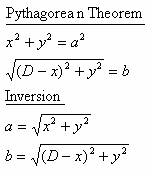
Because of the geometry of our project (diagrammed below), we used the rules of right triangles to determine the change in the hypotenuse of a triangle given changes in the other two sides.
The following math shows how the Pythagorean Theorem was used to find equations for a and b in terms of x and y.
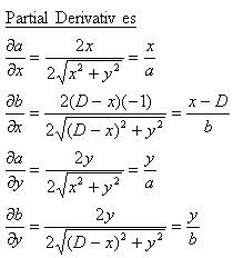
The next equations show the partials derivatives of each string with respect to each dimension.
This last set of equations shows the partial derivatives in Jacobian form.
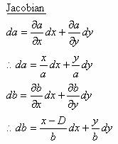
With this last set of equations, we now have a very useful relationship between the changes in the strings and the changes in the coordinates. In fact, this is all we need to make our motors move as desired. Since we will know the current values of a, b, x, and y, and can choose dx anddy as desired, we have all the information necessary to change a and b correctly.
The pen in this project is controlled by the motors, which in turn are controlled by the software. There are four possible modes the user can choose from, free draw, plot coor, plot text, and plot prog. The software uses a large state machine which changes states depending on the current state and the buttons pressed by the user. Based on the state it is in, the software accepts information from the user, prints messages to the LCD, rotates the motors, and turns on/off the solenoid. Because we know the steps the motors takes per centimeter of the string, we are able to keep track of distance on the board. This allows us to indicate when the user is going out of bounds. It is also the key information which allows us to draw lines of specific lengths and angles.
The only real trade-off we were confronted with was related to the speed at which we incremented steps in the motors. We discovered it was much easier to control the drawings and solenoid at slower speeds for the user. Slowing down the motors was also necessary to allow the hardware to physically keep up with the fast-paced software.
There are a couple traditional xy plotters that we have found. The following are the links to the websites for these plotters.
- http://www.graphtecusa.com/products.php?cat_id=2&visit=img
�@ - http://images.google.com/imgres?imgurl=on1djj.rug.ac.be/HP7475-engraver/Plotter.jpg&imgrefurl=http://on1djj.rug.ac.be/HP7475-engraver/&h=300&w=400&sz=35&tbnid=4cmFVmKO9EEJ:&tbnh=90&tbnw=120&start=19&prev=/images%3Fq%3Dpen%2Bplotter%2B%26hl%3Den%26lr%3D%26ie%3DUTF-8%26oe%3DUTF-8%26sa%3DN
The most similar plotter to ours is the one completed in Spring 2001, called the Vertical Plotter.
However, our design is unique because not only is it unconventional by being non-orthogonal, but it is also horizontal.
Hardware Design
The hardware for the Non-Orthogonal Plotter consisted of a 16-key keypad, 16×2 LCD panel, a couple of 12V 7.5 degree unipolar stepper motors, a 12V solenoid, springs and fishing line, and the pen apparatus.
The keypad is wired to PORTB on the microcontroller, and the LCD to PORTC. The two stepper motors are controlled through PORTA, and the pen pickup via the solenoid is handled by PORTD. The overall hardware schematic of the device is as follows.
Each motor was wired to the motor driver (ULN2003) chips as follows. The ULN2003 chips were wired to PORTA (PIN0-3 for the right motor and PIN4-7 for the left motor) as shown below. The bottom of the axles of the motors were lined with washers to prevent any tangling of the fishing lines in the small gaps that were there.
Motor driver pinout
Solenoid
The solenoid was wired to a driver, which consisted of two transistors (TIP31 and Darlington 2N3904), a 1K resistor, and a 12V power supply as shown below. The driver was connected to PIN7 of PORTD.
Pen Apparatus, Fishing Line, and Spring
The pen apparatus was connected to each motor with fishing line and to the bottom of the board through a rubber band which was connected to a spring. This is shown below:
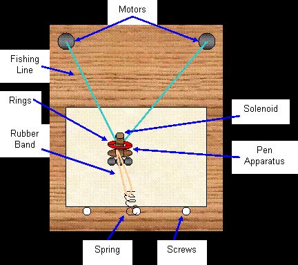
The pen apparatus was made with a cardboard spool. The bottom of the spool was attached to a circular piece of cardboard. The bottom of this was evenly lined with weights to prevent the apparatus from tipping and glued to a ring of ball bearings to allow smooth movements across the sheet. The pen was attached to a solenoid and placed through the center of the spool. We placed a small spring inside the solenoid for pressure during writing.
The starting position of the pen apparatus is towards the bottom of the board, with both fishing lines completely unwound. We encountered several challenges in building this. One of the biggest challenges was to generate enough tension on the spring side of the board to allow the system to work horizontally. We tried various solutions using different spring lengths, multiple springs, only rubber bands, and even tilting the board. The best solution was found in the combination of the spring and rubber band. We also had trouble with the pen apparatus and initially tried spray-can lids and plastic containers. We eventually discovered the spool to be the best solution and managed to find one with perfect inner and outer radii. The pen apparatus was too light in the beginning and was very easily tilted over. To prevent this, we added weights the bottom of the apparatus to make it heavier.
Parts List:
|
Item |
Price |
Item |
Price |
|
Cardboard Spool |
$0.10 |
Springs x 2 |
$0.96 |
|
Ball Bearing Chains |
$0.49 |
Nails x 7 |
$0 |
|
Ball Bearing Ring |
$0.75 |
16-key Keypad |
$0 |
|
Bracelet String |
Less than $0.01 |
16×2 LCD |
$0 |
|
Fishing Line |
Less than $0.01 |
12V Power/Switch |
$0 |
|
Stepper Motors x 2 |
$0 |
ULN2003 Drivers x 2 |
$0 |
|
Washers for Weight |
$0.96 |
Circuitry for Solenoid |
$0 |
|
Tangle-free Washers |
$0.35 |
Solenoid |
$0 |
|
Wooden Board |
$0 |
Rubber Band |
$0 |
For more detail: Non-orthogonal Plotter
- What is the primary function of the Non-Orthogonal Plotter?
The device sketches pictures and prints letters on paper using two stepper motors that control string lengths. - How does the software control the movement of the motors?
The software uses simple calculus and differential equations based on right triangle geometry to determine rotation speed and direction. - Can users draw freely or only use pre-set options?
Users can freely draw in eight different directions, plot line segments of specific length and angle, or choose manufacturer built-in drawings. - Does the project include a feature to lift the pen off the paper?
Yes, a solenoid is included to lift the pen off the paper when desired. - What type of microcontroller ports are used for the keypad and LCD?
The keypad is wired to PORTB and the LCD is connected to PORTC on the microcontroller. - How was the pen apparatus stabilized to prevent tipping?
Weights were added to the bottom of the cardboard spool apparatus to make it heavier and prevent it from tipping over. - What was the best solution found to generate tension for horizontal operation?
The team found that a combination of a spring and a rubber band was the best solution for generating enough tension. - Are there any modes available for printing text?
Yes, the software includes a plot text mode to print upper-case alphabet text and numbers.