Access to medical devices is unequal across the globe, and the COVID-19 pandemic has underscored this fact. During the pandemic the global shortage of ventilators has been especially notable. Access to mechanical ventilation in Low and Middle Income Countries is inadequate. South Sudan, for example, possesses four ventilators in total. Across 84 healthcare facilities in northwest Syria, there are only 11 ventilators. Early in April, a total of ten African countries did not have ventilators at all. Unequal access to mechanical ventilation is important in context of the fact that mechanical ventilation is proven to be useful in treatment of various diseases, from COVID-19, to meningitis, to pneumonia.
Ventilators manufactured for use in High Income Countries take for granted infrastructure available in these countries. Such ventilators often are not appropriate for lower resource settings. Not only is cost a barrier, but Low and Middle Income Countries lack access to medical professionals that can use these devices, hospital resources such as oxygen may not be available, and maintenance can prove difficult if not impossible. AutoLung addresses this issue with its Respiratory Assistance Device (RAD), which is intended to serve as a ventilator alternative.
AutoLung’s RAD is an open source solution intended to be buildable by anyone using AutoLung’s free build instructions. The goal is to empower individuals without the resources to access classic manufacturing chains to build a device their community has identified a need for. All parts can either be locally sourced or are consistently in stock on large online suppliers such as Amazon or Digi-Key. The control software of the AutoLung RAD is run from a Teensy microcontroller, and calibrates each device built so that it operates to AutoLung specifications.
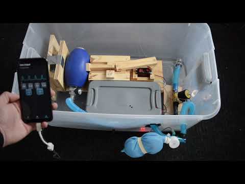
The current device is a non-invasive solution that supplies air to a patient by compressing a Bag Valve Mask using a servo-driven linkage. The AutoLung Android Application can be downloaded from the Google Play Store and run on any Android device. Once the Android is plugged into the RAD, the app can be used to send the control code to the microcontroller, then to calibrate and run the device.
For a 90-second video summary, see here.
***CAUTION: THIS DEVICE IS NOT INTENDED FOR MEDICAL USE. AT THE CURRENT DESIGN PHASE THE DEVICE IS NOT MEANT TO BE A REPLACEMENT FOR AN INVASIVE MECHANICAL VENTILATOR AND SHOULD NEVER BE USED ON ANY PATIENT.
Step 1: Process Overview
Step 2: Tools and Materials List
Tools:
- Saw (Optimally a table saw, miter saw, or other power saw, but if needed could use a hand saw and elbow grease)
- Drill and Hammer
- Sandpaper/Sanding Block
- Soldering Iron
- Wire Stripper (if needed could just use a box knife/other knife)
- Screwdriver (both flathead and phillips)
Mechanism Materials (required)
- 1X: 2×4 Lumber (1′ or greater in length)
- 1X: 3/4″ Thick Plywood (2’x2′ or greater)
- 2X: M3.5 Bolts (Between 22mm to 26mm)
- Wood Screws
- 20X: Short Screws (Between 1″ to 1.25″ long, #6 or #8)
- 10X: Long Screws (Between 1.25″ to 2.25″ long, #6 or #8)
Electrical Parts (required)
- Solder
- 1X: 12V Power Supply (8A or greater)
- 1X: Teensy 4.0 Microcontroller
- 1X: 60kg Servo (6.4V-8V. Must come with hubs. Part number: DS5160SSG)
- 1X: 12V Solenoid Valve (Normally closed, functions for air)
- 1X: Pressure Sensor (Part number: MPX2010DP or MPX2010GP)
- 1X: Flow Sensor (Part number: SFM3300-250-D)
- 4X: Voltage Converters (4.2-40V in to 1.25-37V out, and 5A or greater)
- 1X: 5V Relay Module (Part Number: Funduino MD-002)
- 1X: Analog to Digital Converter (Part number: ADS1115)
- 1X: Logic Level Converter (Part number: BOB-12009)
- 1X: DC-DC Isolating Converter >0.5A 12V-12V DC-DC Isolating Converter. The recommended exact part number is the best choice if using AutoLung’s PCB (Part number: Remcom RS6-1212S)
- Board options (*See below for details on which option is better for you):
- 1X: AutoLung PCB (there are details in electrical instructions on how to order this)
- OR 2X: Perfboard that is 1.875″x2.25″/20×14 or larger.
- 80X: Male Header Pins (0.1” Spacing)
- 50X: Spacing Female Headers (0.1” Spacing)
- 4X: Terminal Blocks (0.2” spacing)
- 2X: 10kOhm Resistors
- 3X: 2000 uF Capacitor (>16V electrolytic capacitor)
- 1X: 4.7 uF Capacitor (>16V electrolytic capacitor)
- 2X: 0.1 uF Capacitor (ceramic capacitor)
- 1X: 2.2 uH inductor (>0.5A)
- 1X: Schottky Diode (>8A diode)
- 1X: 22 Gauge Wire in up to five colors (3-5ft total)
- 1X: 16 Gauge Wire in two colors (3-5ft total)
- 1X: Arduino Power Jack (5×2.1mm Male DC barrel jack to wires)
- 1X: 2.5 x 5.5mm Power Plug to Screw Terminals
- 1X: USB Cable (USB Type A to USB Micro Type A)
- 1X: 4″x6″ of Plywood (can be between 1/2″ and 2″ thick)
- 2X: Zip Ties (6″ or longer)
Tubing Parts (required)
- 1X: Bag-Valve Mask
- 1X: Medical Tubing (Part Number: Vyaire 1795)
- 2X: 1/2″ NPT to 3/4″ barb (1/2″ NPT Male to 3/4″ Barbed Male Fitting)
- Pipe sealant – teflon tape or thread sealant plastic
- Sealing material – self-sealing silicone tape or zip tie
Enclosure Parts (not required)
- 1X: Large plastic bin (30″Lx20″Wx10″H plastic bin or larger
- 1X: Small plastic bin (>12″x6″ but <16″x9″ plastic bin)
To run the device, you will need any Android device (this could be someone’s phone, or a new phone costing <$50USD at Walmart)
*Ordering a PCB is highly recommended for ease of assembly. Instructions here are given assuming that a PCB has been ordered, but an electrical diagram has been included if you wish to build the device on perfboard.
Step 3: Mechanism Assembly – Cutting the Pieces
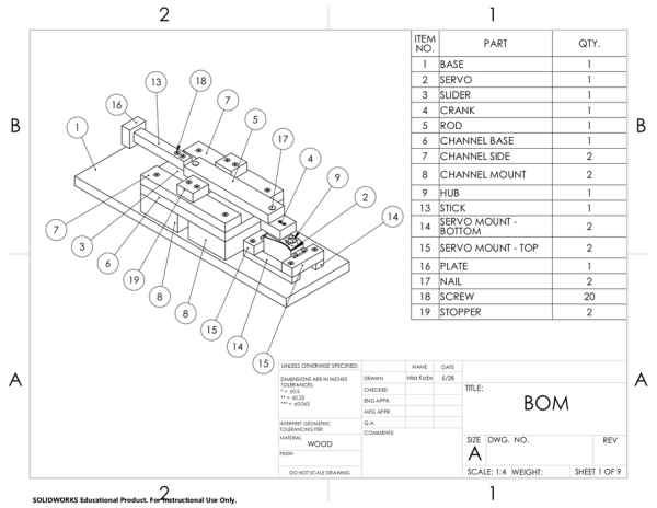
- Download the attached cutting drawings PDF for reference on pieces to cut.
- Using a saw (ideally a power saw), cut the plywood and lumber for the mechanism as specified in the list below. Tolerances are included in the cutting drawings. In general, the most important dimension is the 1.875″ length of the Crank. The lengths of the Stick (4.75″), Slider (3.75″), and Rod (8″) are also important, as is the thickness of the Bottom Servo Mounts (0.5″).
- From the 2″x4″ lumber (See first page of Cutting PDF):
- 2X: Channel Mount – 5.5″ long
- From the 3/4″ thick plywood (See second and third page of Cutting PDF):
- 1X: Channel Base – 8″x5.5″
- 3X: Channel Sides & Rod – 8″x1.5″
- 1X: Stick – 4.75″x0.75″
- 1X: Slider – 2.5″x3.75″
- 1X: Crank – 1.875″x1.5″
- 3X: Plate & Stoppers – 1.5″x1.5″
- 2X: Top Servo Mounts – 1″x3″
- 2X: Bottom Servo Mounts – 4.5″x0.5″
- From the other plywood that can be 1/2″ to 2″ thick (See fourth page of Cutting PDF):
- 1X: Base – 20″x6″
- From the 2″x4″ lumber (See first page of Cutting PDF):
- Sand down especially rough edges on pieces that have been cut. Ensure that the cuts on the Channel Sides and Slider as pictured for this step are especially smooth. If not, sand them further.
Step 4: Mechanism Assembly – Channel Assembly
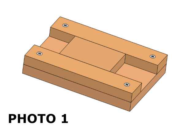
- Assemble the channel (Photo 1). Place the slider between the two Channel Side pieces to ensure they are appropriately spaced. The fit should be close but not too tight.
- Test the Slider by sliding it back and forth through the channel. The fit should be close, but if the Slider is getting caught or takes a great deal of effort to move, re-position one of the Channel Sides to better accomodate the Slider.
- Screw the Channel Mounts under the Channel (Photo 2).
Step 5: Mechanism Assembly – Arm Assembly
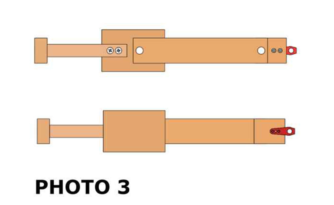
- See attached arm assembly drawings PDF for sizing reference on how to assemble the arm shown in Photo 3.
- Mark and drill pilot holes in the Crank, Rod, and Slider as shown on the first sheet of the arm assembly drawings. These should be much smaller than the diameter of the fastener to be used.
- Align a servo hub to the Crank such that the center of the servo shaft will be along the center axis of the crank. The center of the hub will be 1.78″ from the hole already drilled as shown on the second sheet of the arm assembly drawings. Mark the location of the hub’s two threaded mounting holes on the Crank. The second sheet of the attached drawings shows references for where these are.
- Drill out the holes marked on the crank such that the M3.5 bolts can slide through. Drill counterbores for the M3.5 bolts so that the tops of the bolts will be just flush with top of the wood (Photo 4). The counterbores will be on the top of the Crank, on the side adjacent to the Rod.
- Drill out one of the two holes in the Rod to a size larger than the outer thread diameter of the screws being used.
- Using the drilled holes for alignment, assemble the Slider, Rod, and Crank as shown in the second sheet of the arm assembly drawings (Photo 5). The screw attaching the Rod to the Crank should go through the hole that was drilled out to be larger – the screw will be screwed into the Crank, but the rod should be able to freely rotate.
- Screw the Stick and Plate into the slider crank mechanism assembly (Photo 6). The distance between the end of the Stick/Plate pair to the nearest fastener in the Rod should be 6.25″ as shown in the second sheet of the arm assembly drawings, and the location of the fasteners that attach the Stick to the Slider do not need to be exact.
- The M3.5 bolts screw the servo hub to the Crank (Photo 7). Note that the Crank and Rod have already been attached despite how the Crank is depicted in Photo 7.
- The arm should be fully assembled (Photo 3), but small changes may need to be made if key dimensions do not fall within tolerances as outlined on the second and third sheets of the arm assembly drawings.
Step 6: Mechanism Assembly – Servo Mount
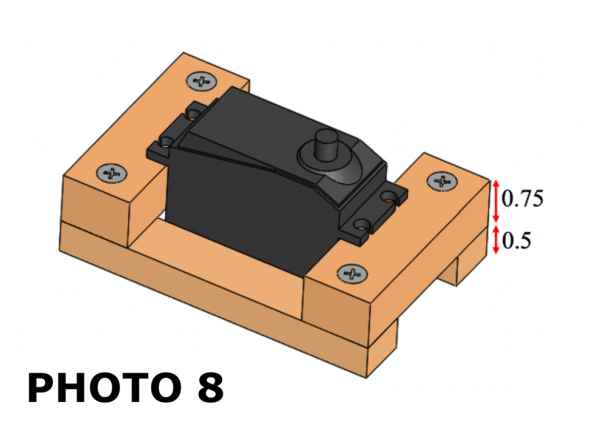
- Assemble the Servo Mount (Photo 8). It is important that the Bottom Servo Mount is turned so that the 0.75″x4.5″ face is touching the ground. Before screwing the mount together, ensure that the servo is placed in the mount, as the servo may not fit in otherwise.
- Line up the mounted channel and mounted servo on any flat surface. Temporarily place the servo hub and attached arm onto the servo, then place the slider in the channel. If the height of the slider is too low or too high, the Rod will be at an angle. The Rod does not have to be perfectly level, but should not be at too great an angle. If alignment is an issue, the bottom servo mounts may have to be re-cut accordingly so that the 1/2″ Bottom Servo Mount is the proper thickness to make your Channel, Servo Mount, and Arm function together.
- Screw the servo into the mount. The screws can stick out the bottom of the Top Servo Mounts.
Step 7: Mechanism Assembly – Final Assembly
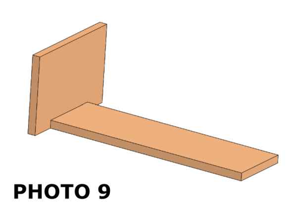
- Align but do not fasten the Bag Mount to the Base (Photo 9). The Bag Mount should be centered on the base, with an edge flush to the bottom of the Base.
- Place the Bag Valve Mask (BVM) against the Bag Mount so that the bottom of the bag is tangent to the Base, and the BVM is roughly centered on the Base. The bag will be fastened to the Bag Mount using four zip ties. Using the BVM as a guide, mark eight holes to drill for the zip ties to go through. Remove the Bag Mount, and drill out the marked holes (Photo 10). Note that Photo 10 depicts the Bag Mount while it is still against the base, even though it has been removed.
- Screw the Bag Mount to the Base (Photo 11).
- Place the channel mount and servo mount on the base so that the assembly is distanced as shown in the attached final assembly drawing PDF. The Channel should be ~6″ away from the Bag Mount, but the tolerances here are wide because Channel location will depend on BVM diameter (which can vary). Place the arm so that the servo hub meshes with the servo shaft and the slider is in the channel. Rotate the arm such that the end of the arm is far from the Bag Mount. The Plate should be as far from the Bag Mount as possible while still protruding out further than the edge of the channel by a small amount. Put the BVM against the Bag Mount. If the Stopper is not lightly touching the BVM move the Servo Mount and Channel so the arm is doing so (Photo 12). Maintain the 0.5″ distance between the Servo Mount and Channel, but change the 6″ distance as needed.
- Remove the servo hub and arm mechanism. Screw the Channel and Servo Mount into the Base.
- Attach the servo hub to the servo and place the Slider in the Channel.
- Screw the two stoppers into the two Channel Sides (Photo 13). The Stopper should overhang the Channel by around 0.25″. Slide the slider back and forth to check that the Stoppers do not interfere with the Rod.
- Zip tie the BVM to the Bag Mount (Photo 14).
Step 8: Electrical Assembly: Overview
The recommended electrical assembly process involves using a PCB. Assembly without a PCB should only be attempted by those with a strong background in electronics and soldering. The PCB provides all the electrical connections. If you cannot acquire or do not want a PCB, connections will have to be made according to the connection diagram attached as an SVG and the connections list below. The steps provided in this Instructable tutorial use a PCB and if you are using a PCB you will not need to reference the connections list or diagram. Manufacturing without a PCB is unadvised as it requires detailed work and takes much longer to complete. For those not experienced with soldering and wiring, the attached electrical techniques PDF provides some background.
The attached SVG PCB diagram shows a list of connections made on the PCB. Connections external to the PCB are listed below.
- 5V Buck Converter
- Mainboard 12V to Vin
- Mainboard GND to GND (in)
- Mainboard 5V to Vout
- Mainboard GND to GND (out)
- 8.4V Buck Converter
- Mainboard 12V to Vin
- Mainboard GND to GDN (in)
- Mainboard 8.4V to Vout
- Mainboard GND to GND (out)
- 5V Isolated-Buck Converter
- Mainboard 12V iso to Vin
- Mainboard GND iso to GNDin
- Mainboard 5V iso to Vout
- Mainboard GND iso to GNDout
- 10V Isolated-Buck Converter
- Mainboard 12V iso to Vin
- Mainboard GND iso to GNDin
- Mainboard 10V iso to Vout
- Mainboard GND iso to GNDout
- Relay/Solenoid Valve
- Mainboard 12V to Relay COM
- Relay Normally Open (NO) to Valve Vin
- GND to Valve GND
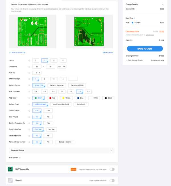
Step 9: Electrical Assembly – Ordering the PCB
If you would like to order a PCB, please use the AutoLungPCBGerber.zip file and upload to your board provider of choice. Download the file here (https://tinyurl.com/autolung-pcb).
We do not recommend any specific board manufacturers but will provide a brief overview of ordering. This overview will use JLCPCB, but many manufacturers provide similar choices and quality.
- Go to jlcpcb.com.
- Click “Quote Now”. Don’t worry about entering any data, just click the button.
- Click “Add gerber file.”
- Check the auto-fill data. The form should autofill data, but if it does not, pictured above are the settings we recommend.
- Checkout as you would on any website.
Step 10: Electrical Assembly – Component Preparation
- Do not connect the Power Supply to the Power Jack. Ensure this remains disconnected until the appropriate step in the Electrical Assembly Process when directed to do so, DO NOT RECONNECT THE POWER SUPPLY UNLESS DIRECTED TO DO SO.
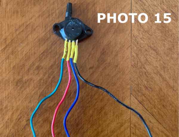
- Prepare the pressure sensor and flow sensor to be hooked up to the system. Wires will need to be soldered to the pins on the pressure sensor (Photo 15). The pin with the divot will be soldered to ground, followed by output+, followed by Vin, followed by output-. The other end of the wires will be soldered to the board in this exact order. Alternatively, the sensor can be directly soldered to the board if in the correct orientation.
- Prepare the flow sensor by soldering a 6-pin set of header pins to the flow sensor (Photo 16). Ensure that there is no solder bridging on the flow sensor.
- Set up the power supply. The power supply should provide 12V output. DO NOT PLUG THE POWER SUPPLY INTO THE SYSTEM WHILE THE BUCK CONVERTER OUTPUTS ARE ATTACHED TO ANY COMPONENTS.
- Add the Schottky diode anti-parallel with the direction of current flow in the solenoid valve (Photo 17). Many valves can be wired with either wire as 12V or GND. To make use of the diode, you must choose a 12V and ground wire on the solenoid. LABEL THESE WIRES SO YOU DON’T CONFUSE THEM. Colored tape works fine to label. GND is usually labelled in black and +12V can be red, but any labelling mechanism is fine. Do not reverse the leads, or you may short your power supply. The white ring on the diode should be positioned facing the 12V connection. This connection requires stripping in the middle of wires as described in the techniques section and soldering the diode in place. Try to place the diode as close to the valve as reasonable. Once placed this connection can be covered with non-conductive tape.
- Before putting them fully in the system, the voltage Converters should be set to 5V, 8.4V, 10V, and 5V (there are two 5V buck converters) with a 12V input. Ensure buck converter outputs are not connected to the system while the buck converters are hooked up to be brought to the appropriate voltage. This should be done by using the screw potentiometer on the Voltage Converter. Use the small flathead screwdriver to turn the screw multiple turns to adjust the voltage up and down. After setting the buck converters to appropriate voltage, DISCONNECT THE POWER SUPPLY FROM THE SYSTEM. Label the buck converters with appropriate voltages so they don’t get mixed up.
Step 11: Electrical Assembly – PCB Preparation
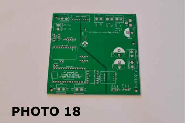
- Start with the bare PCB (Photo 18).
- Solder on the DC power plug (Photo 19).
- Add Terminal Blocks (Photo 20)
- Prepare female header pins (Photo 21). This should include 2X 13-pin sections, 1X 10-pin section, 2X 6-pin sections, and 2X 4-pin sections. An easy way to prepare these is to count out the number of pins needed, and remove the next pin with pliers. The header pins can then be cut at that location with either a cutter or a knife
- Attach female header pins (Photo 22).
Source: Open Source Ventilator Alternative