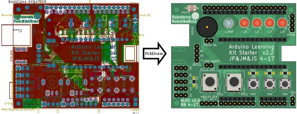
This small Python script takes a KiCAD board (.kicad_pcb file) and produces a 2D nice looking drawing of the board as an SVG file. This allows you to quickly and automatically create awesome pinout diagrams for your project. These diagrams are much easier to read than a labeled photo of a physical board or an actual KiCAD design.
You and your users will love them!
Dependencies
This script requires the pcbnew Python module (should come with KiCAD), the argparse and lxlml modules. No other dependencies are needed.
PcbDraw also needs a module library to work. This library is maintained as a separate repository: PcbDraw-Lib.
Usage
Usage of PcbDraw is simple, just run:
./pcbdraw.py <libraries> <output_file> <input_file>
librariesis a comma separated list of paths to directories containing module libraries. Modules are component footprints in SVG format.output_fileis a path to an output SVG fileinput_fileis a path to an*.kicad_pcbfile
The script will output several debug messages of KiCAD Python API you can ignore. I haven’t found a way to disable them. If there is a missing module in the libraries, the script will output warning.
There are several options for the script:
--style=<JSON_file>specifies color theme for the board. Default is a green board, other styles can be found in thestylesdirectories.--list-componentsprints a list of all components from the front side of PCB. Doesn’t produce drawing.--placeholdershows a red square in the drawing for missing modules.--remaptakes a path to a JSON file containing a dictionary from component references to alternative modules to change a module for given component. This allows you to e.g. choose different colors for LEDs without a need to change original board and create new packages for different colors. Format of dictionary entry is"<ref>": "<library>:<module>"– e.g."PHOTO1": "Resistors:R_PHOTO_7mm".--no-drillholesdo not make the drill holes transparent.
Writing Custom Styles
Style is a JSON file contain color definitions for the board substrate (they don’t have any effect on modules):
{
    "copper": "#417e5a",
    "board": "#4ca06c",
    "silk": "#f0f0f0",
    "pads": "#b5ae30",
    "outline": "#000000"
}
Colors are in HEX format, names of the colors should be self descriptive.
Module Library
Library is a collection of SVG files each containing one drawing of a component. The library structure follows KiCAD library structure – each footprint (module) is a separate file placed in directories representing libraries.
It is also possible to have multiple libraries with different component style.
All the details about the library can be found in its repository. Note that the library is essential for this script and unfortunately it is still incomplete – contributions are welcomed! Drawing a single component from scratch takes less than 10 minutes, which is not much time. Please, send a pull-request for components you have created.
Read more: PcbDraw – KiCAD board into a nice looking 2D drawing