Summary of POV Bike Display – ESP8266 + APA102
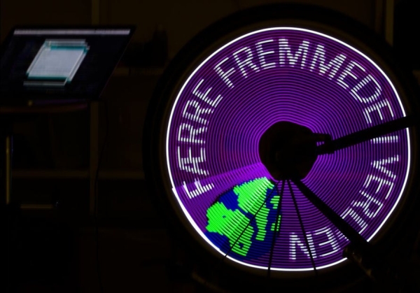
This Instructable details building a low-cost, wireless Point-of-View (POV) bike display using an ESP8266 microcontroller and APA102 LED strips. The project features image stabilization via a reed switch and magnet, allowing users to create moving screen effects on their bicycle wheels. It emphasizes affordability by utilizing cheaper components than commercial alternatives while offering wireless control capabilities through the NodeMCU v2.
Parts used in the POV Bike Display:
- NodeMcu v2
- APA102 led strip (at least 32 pixels)
- APA102 booster pixel
- Reed switch
- Magnet
- 10k ohm resistor
- 3 AA battery clip
- 3 AA batteries
- SPST switch
- 1000uf capacitor
**DISCLAIMER**
This instructable was part of my master’s thesis and is by any means finished. I don’t have a workspace at the moment, so I can’t finish it before I got a proper space to test and build.
If you would like to build a POV bike display feel free to use this as inspiration, but I would recommend you to use the Adafruit guide.
How to turn your bike into a moveable screen in the city? This instructables aims to answer how to do that cheap and easy with parts most makers already have lying around.
Before we start on how to build the device I would like to thank Ada and her guide on making a POV display. I have used the code from her guide as inspiration, a stepping stone and a huge part of her code exists in my example.
The biggest difference is that I have made the code work with the popular WiFi microprocesser, ESP8266. I’m using a NodeMCU v2 in my example which required a lot of tweaking. My main reasoning behind choosing an ESP8266 device is that it is a powerful piece of hardware, and you can implement wireless communication to control the image, synchronize multiple units or whatever you can come up with. Another difference is that I have implemented an image stabilizer that should make the screen more readable when riding the bike (there is a lot room for improvement but if you want a finished and professional consumer product buy POV from Monkeylectric). The last difference is that I’m using cheaper parts in my build. The SK9822/APA102 is basically the same hardware as Adafruit Dotstar but way cheaper. You can get a NodeMCU for only $3.95 if you can wait for it to ship. And now to the guide!!
Step 1: Components
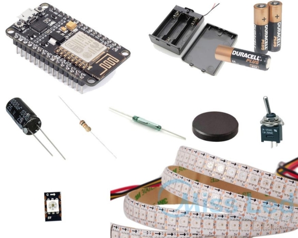
For this build you will need
- 1x NodeMcu v2
- 1x APA102 led strip at least 32 pixel
- 1x APA102 booster pixel
- 1x Reed switch
- 1x Magnet
- 1x 10k ohm resistor
- 1x 3 AA battery clip
- 3x AA batteries
- 1x SPST switch
- 1x 1000uf capacitor
As mentioned above, I chose this microprocessor for various reasons. It is fast, cheap, small, and potential for wireless communication.
These LEDs are super fast and great for projects where timing is a critical factor. Compared to another popular choice WS8212/neopixel it got a clock pin to secure that it doesn’t go off sync. You can also opt for APA102 clones called SK9822. You can split up the strip and both parts are still functional because each pixel got a driver, so when you buy a meter of LEDs for your POV project, the rest can be used for the other wheel of the bike or another project.
Booster pixel:
You need a single APA102 pixel (cut it off at the end of your strip) as close to your NodeMCU as possible. The reason is that the NodeMCU only outputs 3.3 volts and the APA102 operates at 5 volts but if you put a pixel close enough, it works as a Logic Level Converter, so the clock and data signal gets converted to 5v to the rest of the pixels. In the code we never send color to the booster pixel as its only function is to amp the signal, so we don’t need to have the strip close to the NodeMCU. I would like to give a thank to Elec-tron.org for coming up with the idea.
Reed Switch and magnet:
The reed switch gives a pulse every time it passes the magnet, and I’m using this for stabilizing the image while riding the bike. I don’t have a link for where i bought this, because i found it in an old magnetic cat door in an electronics dumpster. We are using the 10k ohm resistor as a pull-down to minimize noise.
The rest:
The capacitor is preventing voltage drop when the strip goes from no color to (as an example) all white.
The batteries only provides 4.5 volts but it’s more than enough to drive the system.
The SPST switch is used to turn the circuit on and off.
PS: some APA102 versions have switched between red and green pin. If you have a GRB instead of RGB your strip flash green when you write red to it. I have used both, so that’s why some of my pictures on github looks weird.
Step 2: The Circuit
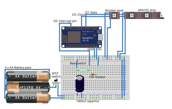
I’ve made the mistake of making long wires from the NodeMCU to the booster pixel in the diagram. It is VERY important to make those wires as short as possible. The distance from booster to the rest of the pixels can be as long as needed. In the diagram and in my version I have placed the capacitor close to the power supply. I would rather place it close to the pixels but both works fine.
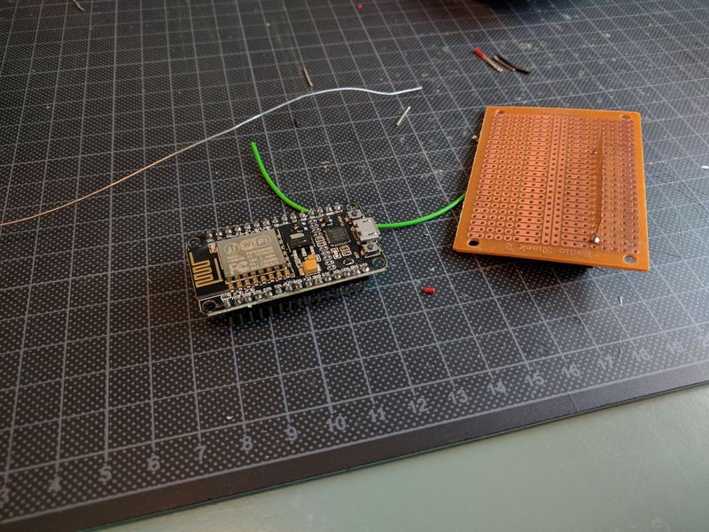
Step 3: Soldering
Step 4: Assembling and Attach to the Wheel
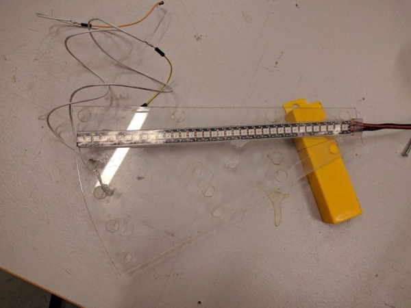
I have made my version into a small package and attached it with a combination of zip ties and duct tape. I would recommend another way to do this because it’s not very practical.
If you want to stabilize the wheel you can attach a second battery pack (in parallel with the first one, circuit wise) on the opposite side.
The magnet is attached to the frame of the bike with hot glue so it aligns with the hall sensor when the wheel rotates.
Step 5: Sketching Images and Concepts
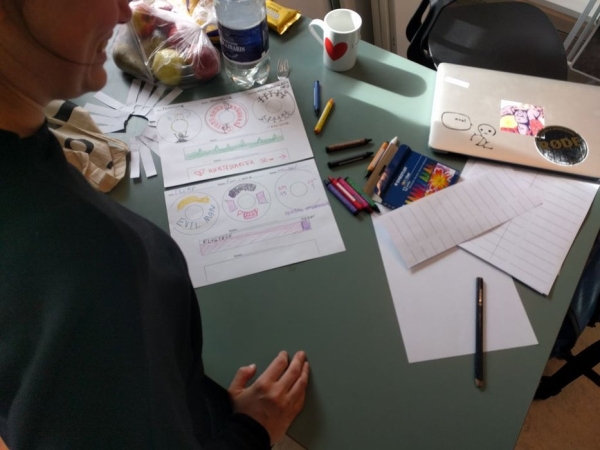
This step consists of making concepts and sketching the image for the bike.
As you can see in the photos this can be done with friends and it might help you to come up with something interesting for your bike wheel. It really helped me/us to discuss our ideas with each other to frame and reframe the message we wanted to send. Remember if you install this it’s not only for you to look at, but everyone you meet on your way. Think of the route you normally take your bike, is there something along that way you want to comment on?
I’ve made a template that might help you coming up with a subject and to design your bike wheel
Step 6: Making Images
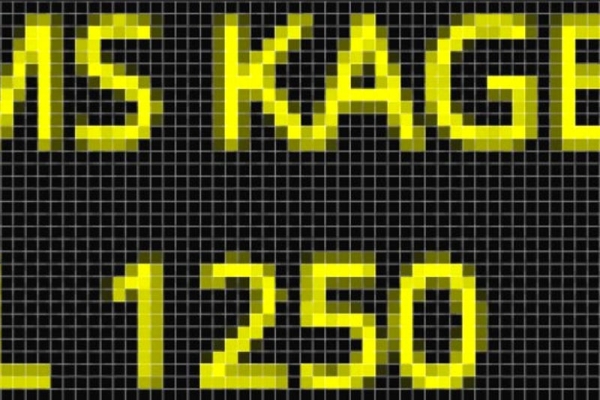
Now it’s time go to photoshop or another image editing program. My images are 84 by 32 pixels because I have 32 pixels in my LED strip and I found that 84 was a good length. You can play around with the width of the photo to find a size that creates the best picture on your bike
When you display your images on your bike it will be stretched in to top of the images and squeezed together at the bottom.
The first four images wont be displayed very well on the wheel and are concept photos that need to be warped to make it fit the POV display better. The last image was used to make the featured image of this instructable and have the right dimensions and is warped to be more readable.
Depending on how you turn your bike and/or on which site you put the leds, you might have to flip the digital image vertically and/or horizontally.
Step 7: Code
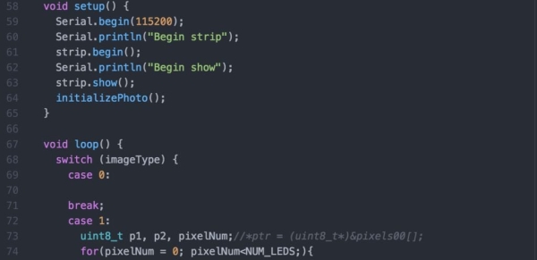
My code can be found on my github.
Source: POV Bike Display – ESP8266 + APA102
- Why was the ESP8266 chosen for this project?
The ESP8266 was selected because it is fast, cheap, small, and supports wireless communication for controlling images or synchronizing units. - How does the circuit handle voltage differences between the microprocessor and LEDs?
A single APA102 booster pixel placed close to the NodeMCU acts as a logic level converter to change the 3.3-volt output to 5 volts for the rest of the strip. - What is the purpose of the reed switch and magnet?
The reed switch pulses when passing the magnet to provide data for stabilizing the image while riding the bike. - Can the APA102 LED strip be cut into smaller pieces?
Yes, you can split the strip because each pixel has its own driver, allowing parts to be used for different projects like the other wheel. - Why is a capacitor included in the build?
The capacitor prevents voltage drops that occur when the LED strip changes from no color to full brightness like all white. - What are the recommended image dimensions for the display?
The author suggests 84 by 32 pixels, though users can adjust the width to find the best picture size for their specific setup. - Does the code support wireless synchronization?
Yes, the ESP8266 hardware allows for wireless communication to synchronize multiple units or control the image remotely. - How should the wires between the NodeMCU and booster pixel be arranged?
These wires must be made as short as possible to ensure proper signal transmission.