
Summary of Power LED Dimmer using ATmega32 Microcontroller
This article details a 1Watt LED dimmer project using an ATmega32A microcontroller. It explains how Pulse Width Modulation (PWM) adjusts brightness by varying the duty cycle, which controls the average voltage delivered to the LED. The circuit utilizes an OC0 PWM channel connected to a TIP127 transistor, with buttons for control and capacitors for debouncing.
Parts used in the 1 Watt LED Dimmer:
- ATmega32 microcontroller
- Power supply (5v)
- AVR-ISP Programmer
- 100uF capacitor
- 1Watt LED
- TIP127 transistor
- Buttons (2 pieces)
- 100nF (104) capacitor (2 pieces)
- 100Ω resistor
- 1kΩ resistor
In this project we are going to use one of the features of ATmega32A to adjust the brightness of 1Watt LED. The method that is used to adjust the speed of LED is PWM (Pulse Width Modulation). The method of PWM is explained here. Consider a simple circuit as shown in figure.
Now if the switch in above figure is closed continuously over a period of time then the bulb will continuously on during that time. If the switch is closed for 8ms and opened for 2ms over a cycle of 10ms, then the bulb will be ON only in the 8ms time. Now the average terminal over across the over a period of 10ms = Turn ON time/ (Turn ON time + Turn OFF time), this is called duty cycle and is of 80% (8/ (8+2)), so the average output voltage will be 80% of the battery voltage.
In the second case, the switch is closed for 5ms and opened for 5ms over a period of 10ms, so the average terminal voltage at the output will be 50% of the battery voltage. Say if the battery voltage is 5V and the duty cycle is 50% and so the average terminal voltage will be 2.5V.
In the third case the duty cycle is 20% and the average terminal voltage is 20% of the battery voltage.
In ATMEGA32A we have four PWM channels, namely OC0, OC1A, OC1B, and OC2. Here we are going to use OC0 PWM channel to vary the brightness of the LED.
Components Required
Hardware:
ATmega32 microcontroller
Power supply (5v)
AVR-ISP Programmer
100uF capacitor,
1Watt LED
TIP127 transistor
Buttons (2 pieces)
100nF (104) capacitor (2 pieces),
100Ω and 1kΩ resistors (2 pieces).
Software:
Atmel studio 6.1
Progisp or flash magic
Circuit Diagram and Working Explanation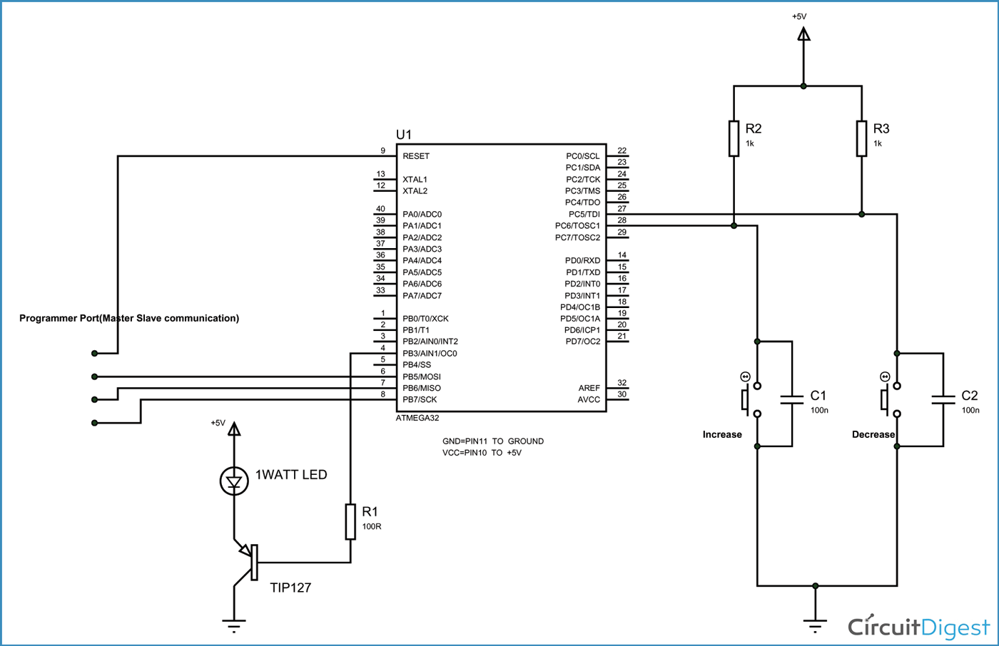
The above figure shows the circuit diagram of LED dimmer.
In ATmega, for four PWM channels, we have designated four pins. We can only take PWM output on these pins only. Since we are using PWM0 we should take PWM signal at OC0 pin (PORTB 3rd PIN). As shown in figure we are connecting the base of transistor to OC0 pin to drive the power LED. Here another thing is over four PWM channels, two are 8-bit PWM channels. We are going to use a 8-bit PWM channel here.
A capacitor is connected to each of the buttons to avoid bouncing. Whenever a button is pressed there will be some noise at the pin. Although this noise stabilizes in milliseconds. For a controller the sharp peaks before stabilization acts as triggers. This effect can be eliminated either by software or hardware, for the program to be simple. We are using hardware method by adding debouncing capacitor.
For more detail: Power LED Dimmer using ATmega32 Microcontroller
- How does PWM adjust the brightness of the LED?
PWM adjusts brightness by changing the duty cycle, which determines the average terminal voltage across the LED over a specific time period. - What is the formula for calculating the duty cycle?
The duty cycle is calculated as Turn ON time divided by the sum of Turn ON time and Turn OFF time. - Which PWM channel is used in this project?
The project uses the OC0 PWM channel to vary the brightness of the LED. - Why are capacitors connected to the buttons?
Capacitors are connected to the buttons to avoid bouncing noise that acts as triggers for the controller when a button is pressed. - What is the function of the TIP127 transistor in the circuit?
The TIP127 transistor is driven by the OC0 pin to power the LED. - What software is required to program the microcontroller?
The required software includes Atmel studio 6.1 and Progisp or flash magic. - Which specific pin provides the PWM signal output?
The PWM signal is taken at the OC0 pin, which corresponds to the 3rd PIN of PORTB. - Can all four PWM channels on the ATmega32 be used for this project?
No, while there are four channels available, this specific project only utilizes the OC0 channel.
