Summary of How to Program in Boot Loader Section
Summary: This project programs simple LED-blink code into the ATmega16 Boot-Loader Section (BLS) and another into the Application Section, demonstrates BLS execution after reset, and then jumps to the application code. It uses AVR Studio to compile with BLS start address 0x1C00, USBasp as the programmer, and AVR-Burnomat to flash the generated hex. Fuse bits must be set to enable internal oscillator and change reset vector to 0x1C00. BLS code can use SPM to self-program flash, enabling bootloader functionality.
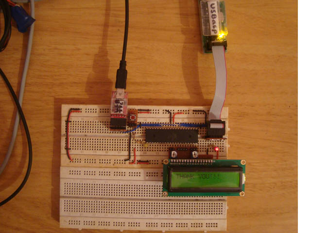
Parts used in the ATMEGA16 Bootloader LED Blink Project:
- ATmega16 microcontroller
- USBasp programmer
- AVR-Burnomat burner software
- AVR Studio IDE (AVR Studio 4 referenced)
- LED (connected to PD7)
- Resistor for LED
- Power supply for microcontroller
- Wires and breadboard or PCB for connections
In the AVR microcontroller the flash memory is divided into two parts, namely Application Section and Boot Loader Section. A code can be programmed into either the Application Section or the Boot loader Section (BLS). The code programmed into the Application section runs normally and is used for common applications, whereas the code running in the BLS is provided with some special features. The code running in the BLS section can execute Self Programing Mode (SPM) instructions which are blocked for the code running in the Application section. Using SPM instructions the code from the BLS can rewrite the code in the application section or the code in the BLS itself. The BLS section is normally used for storing the Boot-loader code for the microcontroller. The Boot-Loader code can be used for initializing the peripherals in the microcontroller, initialize the devices connected to the microcontroller, select the application to load and execute from a storage medium, load the selected application to the application section, jump to the application section and execute the application.

This project tries to program a simple LED blinking code into the BLS and another similar kind of simple code in the Application section and observes the code executing in the BLS and then makes a jump to the Application section code. Programing a simple code into the BLS, make the microcontroller to execute the program in the BLS after a reset and jumping from the BLS to the application code are the initial steps to create a Boot-Loader code for the microcontroller. In this project ATMEGA16 microcontroller is used and AVR studio is used as the IDE. The programmer used in this project is Usbasp and the burner software used is AVR-Burnomat.
The AVR flash memory is divided into two sections namely the application section and the Boot-Loader section (BLS). In case of the ATMEGA16 it has 16 KB of flash memory of which the 15KB is application section and the rest 1KB is BLS. The memory architecture of the ATMEGA16 is shown in the following figure;

The code for the BLS or application section is written as normally does and there is no much difference. The only thing to be careful about is the size of the code binary. It should not be more than 1KB, otherwise it won’t be able to code programmed into the BLS. The following section discusses how to program a code into the BLS of ATMEGA16 microcontroller with the help of AVR studio as IDE, USBasp as the programmer and AVR-Burnomat as the burner software.
Open the AVR studio, copy and paste a simple led blinking code which is given below;
//#######################################################################//
#define F_CPU 8000000
#include <avr/io.h>
#include <util/delay.h>
int main ( void )
{
DDRD |= 0x80;
while(1)
{
PORTD &= 0x7F; //led on
_delay_ms ( 500 );
PORTD |= 0x80; //led off
_delay_ms ( 500 );
}
}
//#######################################################################//
Before compiling the few settings need to be done. Select the target as ATMEGA 16 as shown in the figure.
The code should be compiled in such a way that it will get flashed at the BLS only. For that one need to do the memory settings as shown below. Select the memory as “flash” name the memory as “.text “give the memory address as “0x1C00”.
Now build the code. Once the compilation has been completed a hex file will be generated. The USBASP programmer is currently not supported by the AVR studio 4. Hence software called AVR-BURNO-MAT can be used for flashing the hex file.
One must write the fuse bits before flashing the code so as to enable the features such as to enable the internal oscillator and to select the reset vector as 0x1C00
For more detail: How to Program in Boot Loader Section
- What is the purpose of programming code into the Boot-Loader Section?
To run code with special privileges such as executing SPM for self programming and to provide bootloader functionality like initializing peripherals and loading application code. - How much flash is allocated to the Boot-Loader Section in ATmega16?
1 KB of the 16 KB flash is allocated to the Boot-Loader Section and the remaining 15 KB is the Application Section. - How do you set the compiled code to be placed in the BLS using AVR Studio?
Configure memory settings by selecting flash, name the memory .text and give the memory address 0x1C00 so the binary is placed at the BLS start address. - Can code in the Application Section execute SPM instructions?
No, SPM instructions are blocked for code running in the Application Section; only BLS code can execute SPM. - Which programmer and burner software are used to flash the BLS in this project?
USBasp is used as the programmer and AVR-Burnomat is used as the burner software. - What fuse changes are required before flashing the BLS code?
Write fuse bits to enable the internal oscillator and to set the reset vector to 0x1C00 so the microcontroller starts execution in the BLS. - What must be considered about the size of the BLS hex file?
The binary size must not exceed 1 KB; otherwise it cannot be programmed into the BLS. - Which pin is used for the LED in the provided example code?
The example toggles PD7 (PORTD bit 7) to blink the LED.