Summary of Programming the ATtiny
This tutorial shows step-by-step how to program an ATtiny85 using an Arduino Uno as an ISP. It covers installing the ATtiny core in the Arduino IDE, flashing the ArduinoISP sketch, wiring the ATtiny to the Uno (including a required 10 uF capacitor between reset and GND), selecting the ATtiny85 1MHz board, uploading the blink sketch via Upload Using Programmer, and notes on supported functions and how to set the ATtiny to 8MHz by burning the bootloader.
Parts used in the ATtiny Programming Project:
- Arduino Uno (or another Arduino board)
- ATtiny85 (or equivalent ATtiny chip)
- 10 uF capacitor
- Jumper wires
- Breadboard
- LED
- USB cable for Arduino
- Computer with Arduino IDE installed
This is a tutorial for programming the ATtiny chip. This tutorial will be more in depth than most. I will give you every step and tell you the things nobody told me when I first started programming ATtiny.
Things You’ll Need
– Arduino Uno( Can be done with other boards but I will be using the UNO)
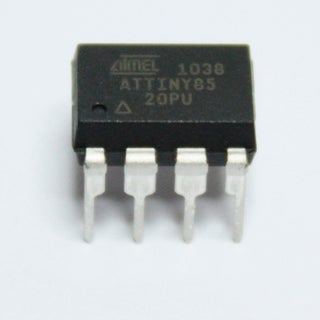
– ATtiny 85 or equivalent
– 10 uF Capacitor
– Jumper wire
– Breadboard
– LED
Step 1: Software
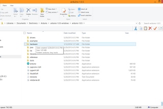
First off, we’re gonna need the software. If you don’t already have it, go to arduino.cc and download the latest version. Next were gonna need to install the ATtiny core files, which are included down below. Open up the arduino software and go to “file” and click on “preferences” take note of you sketchbook location. You’ll need it later. CLOSE the IDE, if you don’t it won’t work until you do. Download the ATtiny core files I’ve included below. Go into the sketchbook and go to the hardware folder. Drag and drop the “tiny” file into that hardware folder. Now reopen the IDE and click on “tools” and then click on “boards”. There should be a whole new set of boards availible including the ATtiny 85. For now, just leave the board as UNO.
Step 2: Arduino As ISP
Now we need to program the Arduino as an ISP( In-System Programmer). To do this go into the examples and look for ArduinoISP. Open this file and upload the sketch to the UNO as you would with any normal sketch. You have now turned the Arduino into an external programmer. One thing you should check is that you have the right programmer selected. To do this go to tools and expand the programmer option towards the bottom. Make sure that Arduino as ISP is selected.
Step 3: Hooking Up the ATtiny to the UNO
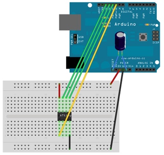
Next step, attach the ATtiny to the Arduino.
Arduino Pin Attiny Pin
10 to 1
11 to 5
12 to 6
13 to 7
5v to 8
GND to 4
*note: See pictures for pin configuration of the tiny
Now you need to put the 10uF capacitor between the reset and GND. Be sure to observe polarity( the small negative signs go to ground).
If you don’t put the cap in there it won’t work.
Step 4: Program the ATtiny
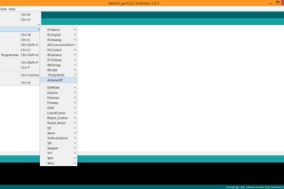
You are now ready to program the ATtiny, but first we need to select our ATtiny chip. To do this, go to “tools” click on “boards” and select the the ATtiny 85 with 1MHz internal oscillator. Don’t use any of the ones that say external oscillator because you need to hookup a external crystal of the frequency. We should check to make sure everything has worked. Go into the examples and open the “blink” sketch change the line “int led = 13”; to “int led = 0”. Now, in order for the sketch to upload you need to go to “file” and click “upload using programmer” it will start uploading and you will get 2 errors that say “avrdude: please define PAGEL and BS2 signals in the configuration file for part ATtiny85” this tells you that the ATtiny has successfully been programmed. Plug in a LED to pin 5(labeled as pin 0) and connect the negative side to pin 4(GND). It should start blinking at 1Hz. Have fun building and creating with your new tinier arduino.
Some things to note about the ATtiny. It doesn’t support all the functions that the UNO does but it does support the following:
– pinMode()
– digitalWrite()
– digitalRead()
– analogRead()
– analogWrite()
– shiftOut()
– pulseIn()
– millis()
– micros()
– delay()
– delayMicroseconds()
– SoftwareSerial
*Another Note: To run the board at 8MHz you must burn the bootloader. To do this, Click on ATtiny 85 with the 8MHz internal oscillator. Click on “tools” and click on burn bootloader. Once that is done the Attiny will run at 8MHz. Doing this will give better timing.
Source: Programming the ATtiny
- How do I add ATtiny support to the Arduino IDE?
Download the ATtiny core files, place the tiny folder into the sketchbook hardware folder noted in Preferences, then restart the IDE to see ATtiny boards under Tools > Boards. - Can I use my Arduino Uno as a programmer for the ATtiny?
Yes, upload the ArduinoISP example to the Uno to turn it into an in-system programmer and select Arduino as ISP under Tools > Programmer. - What wiring is required to connect the ATtiny85 to the Uno?
Connect Arduino pins to ATtiny pins per the tutorial mapping (10->1, 11->2, 12->3, 13->5, 7->8, GND->4) and add a 10 uF capacitor between reset and GND observing polarity. - Do I need the 10 uF capacitor and where does it go?
Yes, place the 10 uF capacitor between the Uno reset and GND with the negative side to ground; without it programming may fail. - How do I upload a sketch to the ATtiny?
Select the ATtiny85 with 1MHz internal oscillator in Tools > Boards, open your sketch, then use File > Upload Using Programmer to program the chip via the Uno. - What indicates that the ATtiny was successfully programmed?
After uploading you may see avrdude errors about PAGEL and BS2; these errors indicate the ATtiny has been programmed successfully per the tutorial. - Which pins does an LED use for the blink example?
Change the led variable to 0 (ATtiny pin labeled 0 corresponds to physical pin 5) and connect the LED positive to that pin and negative to pin 4 (GND). - What Arduino functions are supported on the ATtiny?
The ATtiny supports pinMode, digitalWrite, digitalRead, analogRead, analogWrite, shiftOut, pulseIn, millis, micros, delay, delayMicroseconds, and SoftwareSerial (with limitations). - How do I run the ATtiny at 8MHz instead of 1MHz?
Select ATtiny85 with 8MHz internal oscillator and use Tools > Burn Bootloader to set the chip to run at 8MHz.