Summary of Pull-up Resistors explained
This article explains the purpose and selection of pull-up resistors in microcontroller circuits to prevent floating input pins. It details how these resistors maintain a stable high state when buttons are unpressed and ensure a low state when pressed, preventing short circuits. The text covers resistor value selection (typically 10kΩ), internal MCU pull-ups, RC filter effects on signal speed, and calculations using Ohm's Law to limit current.
Parts used in Pull-up Resistor Project:
- Microcontroller Unit (MCU)
- Pull-up resistor
- Button or switch
- VCC (High voltage source like 3.3V or 5V)
- Ground connection
What is a Pull-up Resistor
Let’s say you have an MCU with one pin configured as an input. If there is nothing connected to the pin and your program reads the state of the pin, will it be high (pulled to VCC) or low (pulled to ground)? It is difficult to tell. This phenomena is referred to as floating. To prevent this unknown state, a pull-up or pull-down resistor will ensure that the pin is in either a high or low state, while also using a low amount of current.
For simplicity, we will focus on pull-ups since they are more common than pull-downs. They operate using the same concepts, except the pull-up resistor is connected to the high voltage (this is usually 3.3V or 5V and is often refereed to as VCC) and the pull-down resistor is connected to ground.
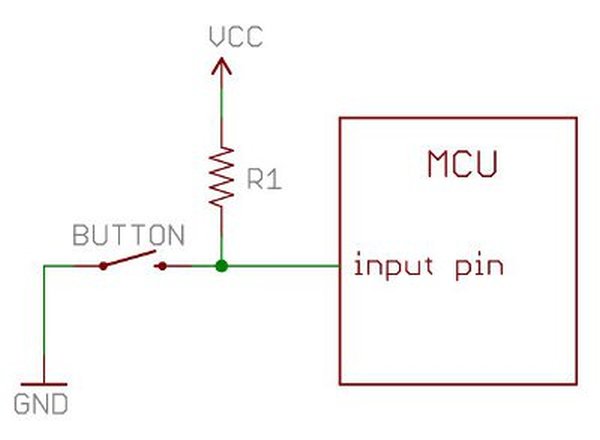
Pull-ups are often used with buttons and switches.
With a pull-up resistor, the input pin will read a high state when the button is not pressed. In other words, a small amount of current is flowing between VCC and the input pin (not to ground), thus the input pin reads close to VCC. When the button is pressed, it connects the input pin directly to ground. The current flows through the resistor to ground, thus the input pin reads a low state. Keep in mind, if the resistor wasn’t there, your button would connect VCC to ground, which is very bad and is also known as a short.
So what value resistor should you choose?
The short and easy answer is that you want a resistor value on the order of 10kΩ for the pull-up.
The value of the pull-up resistor needs to be chosen to satisfy two conditions:
- When the button is pressed, the input pin is pulled low. The value of resistor R1 controls how much current you want to flow from VCC, through the button, and then to ground.
- When the button is not pressed, the input pin is pulled high. The value of the pull-up resistor controls the voltage on the input pin.
For condition 1, you don’t want the resistor’s value too low. The lower the resistance, the more power will be used when the button is hit. You generally want a large resistor value (10kΩ), but you don’t want it too large as to conflict with condition 2. A 4MΩ resistor might work as a pull-up, but its resistance is so large (or weak) that it may not do its job 100% of the time.
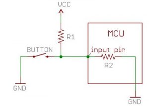
The general rule for condition 2 is to use a pull-up resistor (R1) that is an order of magnitude (1/10th) less than the input impedance (R2) of the input pin. An input pin on a microcontroller has an impedance that can vary from 100k-1MΩ. For this discussion, impedance is just a fancy way of saying resistance and is represented by R2 in the picture above. So, when the button is not pressed, a very small amount of current flows from VCC through R1 and into the input pin. The pull-up resistor R1 and input pin impedance R2 divides the voltage, and this voltage needs to be high enough for the input pin to read a high state.
For example, if you use a 1MΩ resistor for the pull-up R1 and the input pin’s impedance R2 is on the order of 1MΩ (forming a voltage divider), the voltage on the input pin is going to be around half of VCC, and the microcontroller might not register the pin being in a high state. On a 5V system, what does the MCU read on the input pin if the voltage is 2.5V? Is it a high or a low? The MCU doesn’t know and you might read either a high or a low. A resistance of 10k to 100kΩ for R1 should avoid most problems.
Since pull-up resistors are so commonly needed, many MCUs, like the ATmega328 microcontroller on the Arduino platform, have internal pull-ups that can be enabled and disabled. To enable internal pull-ups on an Arduino, you can use the following line of code in your setup() function:
pinMode(5, INPUT_PULLUP); // Enable internal pull-up resistor on pin 5Another thing to point out is that the larger the resistance for the pull-up, the slower the pin is to respond to voltage changes. This is because the system that feeds the input pin is essentially a capacitor coupled with the pull-up resistor, thus forming a RC filter, and RC filters take some time to charge and discharge. If you have a really fast changing signal (like USB), a high value pull-up resistor can limit the speed at which the pin can reliably change state. This is why you will often see 1k to 4.7KΩ resistors on USB signal lines.
All of these factors play into the decision on what value pull-up resistor to use.
Calculating a Pull-up Resistor Value
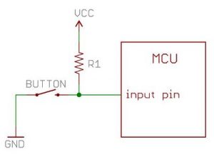
Let’s say you want to limit the current to approximately 1mA when the button is pressed in the circuit above, where Vcc = 5V. What resistor value should you use?
It is easy to show how to calculate the pull-up resistor using Ohm’s Law:
![]()
Referring to the schematic above, Ohm’s Law now is:
![]()
Rearrange the above equation with some simple algebra to solve for the resistor:
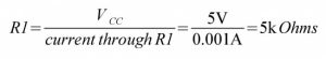
Remember to convert all of your units into volts, amps and Ohms before calculating (e.g. 1mA = 0.001 Amps). The solution is to use a 5kΩ resistor.
For more detail: Pull-up Resistors explained
- What is the primary purpose of a pull-up resistor?
To prevent floating input pins by ensuring they stay in a defined high or low state while using low current. - What is a recommended resistor value for a pull-up resistor?
A value on the order of 10kΩ is generally recommended to balance power usage and signal reliability. - How does a pull-up resistor behave when a button is not pressed?
The input pin reads a high state as a small amount of current flows from VCC through the resistor to the pin. - What happens to the input pin when the button is pressed with a pull-up resistor?
The pin connects directly to ground, causing current to flow through the resistor to ground and reading a low state. - Can microcontrollers have built-in pull-up resistors?
Yes, many MCUs like the ATmega328 have internal pull-ups that can be enabled using specific code commands. - How does resistance value affect response speed?
Larger resistance values slow down the pin's response to voltage changes because the system acts as an RC filter. - Why might a 4MΩ resistor be unsuitable for a pull-up?
Its resistance is too large and weak, potentially failing to pull the input pin high enough for the MCU to register correctly. - What is the general rule for selecting a pull-up resistor relative to input impedance?
The pull-up resistor should be an order of magnitude less than the input impedance of the pin. - How do you calculate the resistor value to limit current to 1mA at 5V?
Using Ohm's Law, the calculation results in a required resistor value of 5kΩ. - Why are lower resistance values like 1k to 4.7KΩ used on USB lines?
These values are used because fast-changing signals require faster pin response times which higher resistances cannot support.