
Summary of RFID interfacing with AVR microcontroller (ATmega16) using interrupts
This article explains how to read a 12-byte RFID tag ID using an AVR microcontroller's serial interrupt and display it on an LCD. Unlike the polling method, interrupts prevent the microcontroller from being busy-waiting, ensuring efficient data handling. The code uses an Interrupt Service Routine (ISR) triggered by the USART_RXC event to store each received byte and immediately write it to the LCD, resetting the counter after every 12 bytes to handle new tags.
Parts used in the RFID Interfacing Project:
- RFID module
- LCD
- AVR microcontroller (ATmega16)
- Serial interrupt mechanism
- Temporary variable for storage
This article covers how to extract and display the twelve byte unique tag ID received by RFID module on LCD using interrupt method. Before proceeding to this article readers must have knowledge of serial interrupt and LCD. In the previous article of RFID, polling method was used where the microcontroller was continuously monitoring the RXC flag. Keeping the microcontroller busy in monitoring the flag is not a good programming technique, so instead of polling method a programmer should prefer using interrupts.
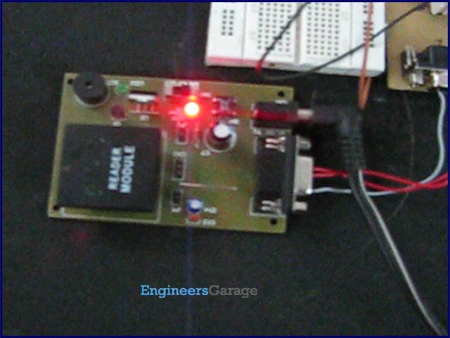
Since the output data of the RFID module uses RS232 protocol and is serial in nature, serial interrupt is used to receive the twelve byte unique ID. Whenever an RFID tag comes in the proximity of the RFID reader module, the module transmits the twelve byte unique ID. Every time one byte of data is received, the controller is interrupted and the corresponding ISR gets executed, which stores the byte in a temporary variable and sends it to the LCD for display.
Since the length of the tag is twelve characters (and hence the serial interrupt will be generated twelve times one after the other) it must be noted that while defining ISR it should not be too long or consume more time. If ISR executes for a longer time then it may skip some data in case another interrupt is generated. In simple words the first ISR would not have executed completely and second ISR will be generated. This would cause data loss.
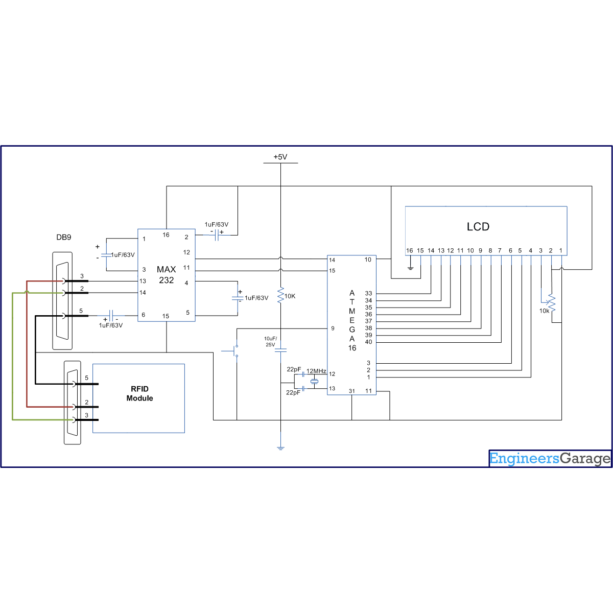
The following is an ISR for the serial interrupt. When an interrupt is received, the variable get incremented and if the value of i is greater the 13, the incoming serial value will start writing from 0th position of second line. Since the unique id of the tag coming from RFID module is of twelve byte so, when the value of variable ‘i’ reaches 12 (i= 12) it means that one set of data is complete and the next coming value of data must be from next card.
ISR (USART_RXC_vect)
{
i++;
if(i==13)
{
i=1;
LCD_cmd(0xC0);
}
value = UDR; // Put the received byte value into the variable “value”
LCD_write(value); // write receive data to LCD
}
-
Why is the interrupt method preferred over the polling method?
The interrupt method prevents the microcontroller from being continuously busy monitoring the RXC flag, which is considered a poor programming technique. -
What protocol does the RFID module output data use?
The output data of the RFID module uses the RS232 protocol and is serial in nature. -
How many times is the serial interrupt generated for a single tag?
The serial interrupt is generated twelve times because the length of the tag is twelve characters. -
What happens if the ISR executes for too long?
If the ISR takes too long, it may skip data because a second interrupt could be generated before the first one finishes executing. -
When does the code reset the index variable 'i' to zero?
The variable 'i' resets when its value reaches 13, indicating that one complete set of twelve bytes has been processed. -
Where does the display start writing when the variable 'i' is greater than 13?
The incoming serial value starts writing from the 0th position of the second line of the LCD. -
What specific vector is used for the serial interrupt in the code?
The code uses the ISR (USART_RXC_vect) vector for handling the serial interrupt.
