Summary of Rhythm Ring: Interactive Rhythm Sequencer Using Atmega32
The Rhythm Ring is a tangible interactive rhythm sequencer designed for Cornell University's ECE 476 course. It allows users to create and modify beats by moving steel ball bearings into holes on three concentric tracks, which represent snare, hi-hat, and bass drum sounds. The device uses an embedded sensor network to detect bearing positions and drives LEDs via Charlieplexing to provide visual feedback of the playhead and active notes. Audio is synthesized using pre-calculated lookup tables stored in flash memory to ensure real-time performance on the microcontroller.
Parts used in the Rhythm Ring:
- Foamcore Board (30"x20")
- Mux: 8:1 3-state 16-DIP
- Mux: 16:1 Analog 28-SOIC
- Steel Balls: 0.75" D
- Superbright LED: 5mm Yellow 3000mcd
- Superbright LED: 5mm Blue 3900mcd
- Superbright LED: 5mm White 5000mcd
- LED: 5mm Green
- Atmel ATmega32
- Power Supply
- ECE 476 Custom PCB
- 8-bit DAC: National Semi DAC0808
- Header Sockets/Pins
- Small Solder Board (2")
- Component PCB (Various Sizes)
- Cardboard Box
I. Introduction
The Rhythm Ring interactive rhythm sequencer is an engaging musical device that enables the user to create a plethora of rhythms and beat patterns with the touch of their own fingers.
Besides being fun to play with, the Rhythm Ring provides a tangible method of arranging a musical rhythm. In our design, the user can arrange beats and modify them in real time by moving steel ball bearings between holes—a physical representation of notes on a musical staff. The Rhythm Ring continuously loops up to three tracks, each with its own voice. A central ring of LEDs provide the user with live feedback for current “playhead” position, and bright LEDs pulse when a note is played due to a detected bearing. The three tracks allow the playback of three different percussion sounds: snare, hi-hat, and bass drum.
We designed and built this device as a five-week final project for ECE 476 at Cornell University.
II. High Level Design
Rationale and Inspiration
The goal of this project is to provide a tangible means of arranging a continuous, dynamic rhythm. An arranger no longer needs to play a traditional musical instrument or use PC-based music software to experiment with rhythms—our device can encourage experimentation through direct, physical manipulation. The arranger can also speed up or slow down the tempo by pressing control buttons on the unit.
The inspiration for this project derives from our mutual interest in music and rhythm. Hanson plays electric guitar, baritone horn, and drums, while Brian plays the acoustic guitar and practices step dance. Because of our enjoyment of and curiosity for arranging and playing music, we decided to design a musical device as our final project. Another source of inspiration was the design and implementation of a more sophisticated sequencer called the BeatBearing, created by Mr. Peter Bennett at the Sonic Arts Research Centre at Queens University Belfast. He is an innovator of interactive devices and has been promoting the concept of the Tangible User Interface (TUI).
Concept
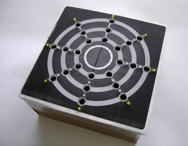
A platform contains three concentric circular tracks, with each track representing a different synthesized sound. Ball bearings can be placed in eight equally-spaced holes on each track. An embedded sensor network detects if ball bearings are present in any of the 24 holes (eight holes per track). The sensor network is composed of a series of wire pairs. Each hole has one wire along the edge of each half the circle. When a conductive steel ball bearing is placed in a hole, it connects the two wires around the hole’s rim.
When the device is turned on, it begins at a pre-defined position on the circle and sweeps along the tracks in a circular motion. As it sweeps around the circle, it keeps track of the current position along the circumference of the circle. In the center of the board, there are 32 green LEDs (later reduced to 16) arranged in a circle with only one of the LEDs lit at a time, showing the current position.
Since the holes are equally spaced throughout the circular tracks, the position of each hole can be calculated by dividing the length of the track into eight segments. We can then define these positions and compare them with the current position counter in the program. When the program reaches one of the eight predefined positions, it will check for the presence of a ball bearing in any of the three tracks at that position. If the program detects a ball bearing in a particular track, it will play the corresponding sound and flash the LED near the ball bearing. If multiple tracks have ball bearings at that position, it will superimpose the sounds by summing their audio samples. When the program reaches the original position on the circle at which it began, it repeats the loop and continues operating until the device is turned off or reset.
Background Mathematics
The bulk of the mathematics necessary for this project involves audio synthesis and signal processing. The rest of the mathematics used consist of simple algebraic computations and timing calculations for Timer 0 and Timer 2. We describe specific calculations for Timer 0 and Timer 2 configurations in the Program Design section.
Audio Synthesis of Percussion Sounds
We began by looking at the spectral content of some recorded percussion sounds from Apple’s GarageBand creative music application and then Fourier-analyzing them in the open-source audio editor Audacity. Unlike plucked strings, percussion instruments do not have a simple wave-like form. Drum sounds typically contain many frequencies, as shown by the peaks in the frequency spectrum highlighted with red lines in the plot below. This implies that such a sound could be synthesized using multiple sinusoids.
Looking at the time domain of the audio signal, we see an exponential decay until the sound dies out completely and becomes silent. With percussion sounds, these decays tend to be faster and less regular than those of plucked strings. Additionally, percussion sounds tend to have a large “attack,” followed by a fast decay at the beginning and then a slower decay after the beginning portion of the signal.
After weeks of experimentation and analysis, we came to the conclusion that the Karplus-Strong (KS) algorithm and Direct Digital Synthesis (DDS) may require too much computation time to produce even moderate-quality percussion sounds within the roughly 720 cycles between each 22.050 kHz sampling deadline. We initially planned to use a 44.100 kHz sampling rate, since that would allow us to reproduce up to 22.050 kHz frequencies (the Nyquist limit for perfect reconstruction), but we scaled back to a sampling rate of 22.050 kHz in order to free up processor cycles for all the other computations necessary for our project. In addition to being set back by the limited computing power of our MCU, the acoustic theory behind the KS method seemed to be beyond the grasp of our understanding as we struggled to produce a range of good-quality percussion sounds.
Instead, we decided to take what we learned from our experimentation with the KS algorithm and DDS to develop a simpler audio generation method (avoiding floating point operations and division) that can produce an acceptable-quality percussion sound. By summing sinusoids of various frequencies close to the ones found in the recorded-instrument frequency spectrums, and by using various fast and slow decay factors, we generated MATLAB code to generate audio waves suitable for sampling at 22.050 kHz. The following is an excerpt from our bass drum sound synthesis MATLAB method:
n = 4000;
for j=1:n/2
slowdecay(j) = 1-j/(n/2);
end
for j=1:n/200
fastdecay(j) = 1-j/(n/200);
end
for j=1:n
bass[j] = slowdecay(j)*(sin(0.018*j) + sin(0.022*j)) + fastdecay(j)*(sin(1.2*j) + sin(5.5*j)
end
We then sum multiple sinusoids together using the equation: sin((f/fs)n + 2π), where f is the frequency of the sinusoid and fs is the sampling frequency. Next, we apply decay factors by setting up an exponential multiplier: multiplier = 1 – (1/b), where b is larger than 1 but smaller than the sample size.
To further reduce the audio output routine resource footprint, we decided to pre-calculate 4000-sample wave lookup tables for each instrument using code similar that of the excerpt above (full MATLAB code for table generation is in the Appendix). We defined each sample table as an array of unsigned chars and stored each array in flash memory, filling 12kB of memory on top of our program code. Since our program only occupies about 4kB without the lookup tables, we are not in danger of hitting the 32kB flash memory limit.
We also considered the math necessary to convert these digital samples to an analog audio signal. Since these values are stored as lookup tables in the program, we first set them as unsigned chars ranging from 0-255 with a base level of 127. We then feed the samples into the DAC, which converts them to a positive analog current. Finally, a large capacitor removes the DC component resulting from the offset of 127, giving us an equal positive- and negative-range audio signal.
Another consideration was the possibility of clipping due to superimposing up to three sound samples at a time (if all three tracks have ball bearings present at one position). To avoid distortion due to overflow in this situation, we divide all samples in the lookup tables by 4 by shifting right by 2 bits. Since shifting right by 2 is much faster than dividing a value by 3, we accept the small loss in dynamic range in exchange for reduced MCU overhead.
Standards
The primary standard to which we adhered involves the protection of users from eye safety hazards. The IEC 825-1 (International Electromechanical Commission) “Eye Safety Classification of Some Consumer Products” describes specifications for laser and LED emission safety requirements to minimize risk of retinal damage. The wavelength, exposure duration, pulse characteristics, distance from the eye, and image size of any laser or LED light source are all factors that can affect the safety of a consumer product that uses such components. Because we use superbright LEDs in our project, we complied with the safety standards addressed in IEC 825-1 while developing the code and determining the LED placement. We reduced the intensity of and exposure to the LEDs by either diffusing them through a medium in the case of the playhead LEDs (although these LEDs emit a very safe amount of light), or by pointing them away from the user in the case of the superbright bearing LEDs.
Relevant Existing Patents, Copyrights and Trademarks
The concept of this project derives from an innovative project called BeatBearing, designed and created by Peter Bennett, a Ph.D. student working in the Sonic Arts Research Centre at Queens University Belfast. The project uses a tangible user interface to implement a rhythmic sequencer.
Charles Allen from Maxim-IC discovered the technique of Charlieplexing to specifically drive a large number of LEDs using relatively few input/output pins on a microcontroller. The technique is formally documented on Application Note 1880 (AN1880) from Maxim-IC.
III. Design Implementation
Hardware Design
Platform (Human Interface Board) Construction
The Rhythm Ring’s physical interface platform is based on an Elmer’s one-sided adhesive foamcore board that measures 11” x 11” x 0.25” (cut with an X-acto model-building saw). We designed the layout of the tracks and the other components using Adobe Illustrator and printed the layout to use as a temporary construction mask by taping it to one side of the board.
After applying the temporary mask, we cut out the holes on the tracks with a Swiss Army knife to make coarse cuts, and a Dremel tool to sand the rim of the circle. The playhead holes (the 16 smaller holes in the innermost ring) were drilled using a small drill bit on the Dremel. We drilled these holes through the foamcore, but unlike the bearing holes, we left the playhead LED holes covered by our final decal. This allowed us to diffuse the LEDs by placing them right underneath the printed decal so that the playhead LEDs would not compete for attention with the track LEDs.
Once all holes were drilled, we printed and applied our final decal. We carefully cut the bearing holes out of the paper with a Swiss Army knife.
Sensor and LED Networks
With the track holes drilled, two exposed wires were placed in each hole to construct the sensor network. The end of one wire is curled along the edge of one half of the hole, while the end of the other wire is curled along the other half. These wires were placed in all 24 bearing holes (8 per track). These sensors must allow the microcontroller to detect if a ball bearing is present. To do this, we use the 0.75″-diameter steel ball bearings to connect the two exposed wires in each hole, pulling the voltage at the tapped junction up to Vcc. When no ball is present, a 330Ω resistor pulls the junction down to ground. Each sensor junction is connected to one input of an 8:1 mux (we use one mux per track). To detect a bearing at a certain location, we use the mux to select that particular sensor and send the voltage at that point to an input pin on the MCU. Charlieplexing allows N pins to selectively drive N(N-1) LEDs.
Charlieplexing
With a limited number of input/output pins on the ATMega32, our design leverages a circuit technique called Charlieplexing. Charlieplexing allows a network of LEDs to be driven using fewer I/O pins than if they were directly connected one-to-one with each pin. The key concept in Charlieplexing is utilizing the high impedance state of our MCU’s tri-state pins. On the ATMega32, an input/output pin can be switched to high impedance mode by setting it to an input.
| Active LED | PIN A | PIN B | PIN C | PIN D |
| LED1 | 0 | 1 | Z | Z |
| LED2 | 0 | Z | 1 | Z |
| LED3 | 0 | Z | Z | 1 |
| LED4 | 1 | 0 | Z | Z |
| LED5 | Z | 0 | 1 | Z |
| LED6 | Z | 0 | 1 | Z |
| LED7 | 1 | Z | 0 | Z |
| LED8 | Z | 1 | 0 | Z |
| LED9 (Unused) | Z | Z | 0 | 1 |
Table 1: Truth table for LEDs using Charlieplexing with 4 pins.
With Charlieplexing, 4 pins can be used to individually turn on a maximum of 9 LEDs. In our implementation, we use four pins to control only eight LEDs (four pins control one of three 8-LED tracks). Charlieplexing works in this implementation by setting only one of the four pins high so that only one of the nine LEDs turn on. To implement our track LEDs, we make three Charlieplexed LED networks and we allow only one LED to turn on per track. Figure 19 in the Appendix shows the three networks connected to the ATMega32 ports.
For example, if we want LED1 to turn on, the program will set PINA to output low, PINB to output high, and PIN C and D to inputs (high impedance). As one can determine from Figure 19, LED1 will get a positive voltage across it, turning it on. All of the other LEDs will have either a voltage of ≤0V across them or a pin at high impedance, causing them to remain off.
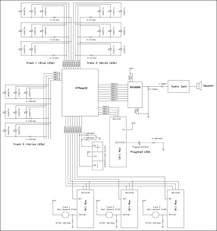
We calculated the resistor values using the typical forward voltage drop and current handling specifications from the manufacturer. For example, the blue superbright LEDs have a maximum reverse voltage of 5V (perfect for our application), a typical forward voltage drop of 4V, and a continuous current rating of 20mA. Since we are supplying 5V to the LEDs, we calculate the necessary drain resistance using Ohm’s law: (5V – 4V)/20mA = 50Ω. We use a 75Ω resistor since they are readily available and using a higher drain resistance is safe (the LED will simply run at less-than-maximum brightness, which is acceptable and possibly safer for superbright LEDs).
Parts List:
| Item | Unit Cost | Quantity | Total Cost | Source |
| Foamcore Board (30″x20″) | 1.25/1 | 1 | 1.25 | Cornell Store |
| Mux: 8:1 3-state 16-DIP | 0.50/1 | 3 | 1.50 | Digi-Key |
| Mux: 16:1 Analog 28-SOIC | 5.72/1 | 1 | 5.72 | Digi-Key |
| Steel Balls: 0.75″ D | 11.48/25 | 25 | 11.48 | McMaster-Carr |
| Superbright LED: 5mm Yellow 3000mcd | 0.20/1 | 8 | 1.60 | MPJA |
| Superbright LED: 5mm Blue 3900mcd | 0.25/1 | 8 | 2.00 | MPJA |
| Superbright LED: 5mm White 5000mcd | 0.20/1 | 8 | 1.60 | MPJA |
| LED: 5mm Green | 1.95/100 | 16 | 0.31 | MPJA |
| Atmel ATmega32 | 8.00/1 | 1 | 8.00 | 476 Lab Stock |
| Power Supply | 5.00/1 | 2 | 10.00 | 476 Lab Stock |
| ECE 476 Custom PCB | 5.00/1 | 1 | 5.00 | 476 Lab Stock |
| 8-bit DAC: National Semi DAC0808 | 1.74/1 | 1 | 1.74 | 476 Lab Stock |
| Header Sockets/Pins | 0.05/1 | 74 | 3.70 | 476 Lab Stock |
| Small Solder Board (2″) | 1.00/1 | 1 | 1.00 | 476 Lab Stock |
| Component PCB (Various Sizes) | Unknown | 2 | 0.00 (salvaged) | Spare Parts Box |
| Cardboard Box | Unknown | 1 | 0.00 (salvaged) | Home |
| Blood, Sweat, and Tears | Priceless | 5 weeks | Undefined | Brian & Hanson |
| Grand Total | 54.90 |
For more detail: Rhythm Ring: Interactive Rhythm Sequencer Using Atmega32
-
How does the device detect ball bearings?
The device uses wire pairs in each hole that connect when a conductive steel ball bearing is placed inside, pulling the voltage up to Vcc. -
What sounds can the Rhythm Ring play?
The three tracks allow the playback of three different percussion sounds: snare, hi-hat, and bass drum. -
How many LED pins are required for the track lights?
The design uses four pins to control eight LEDs per track using the Charlieplexing technique. -
Why was the sampling rate set to 22.050 kHz?
The team scaled back from 44.100 kHz to free up processor cycles for other computations due to limited MCU power. -
How does the system prevent audio distortion?
To avoid clipping when superimposing three sounds, all samples in the lookup tables are divided by four by shifting right by two bits. -
Where are the audio wave data stored?
The 4000-sample wave lookup tables for each instrument are defined as arrays of unsigned chars and stored in flash memory. -
What safety standard did the project adhere to regarding LEDs?
The project complied with IEC 825-1 specifications for eye safety to minimize risk of retinal damage from LED emission. -
Can the tempo of the rhythm be changed?
Yes, the arranger can speed up or slow down the tempo by pressing control buttons on the unit.