Summary of Serial Monitor With ILI9341 and BluePill
This article details a portable serial monitor built on a Blue Pill (STM32F103C8) with an ILI9341 parallel display. It replaces PC software like Putty by offering 9 lines of 28 characters, adjustable baudrates (2400–256000), and USB-free operation powered by a single Lithium-Ion battery. The project features a rotary encoder for baudrate changes, hardware debouncing, and direct register access to optimize display speed.
Parts used in the Serial Monitor:
- ILI9341 display (parallel version)
- BluePill board (STM32F103C8 microcontroller)
- 74HC14 hex inverting schmitt trigger
- 3.3V low dropout voltage regulator
- Rotary encoder (with or without button)
- Lithium ion battery (e.g., from old telephone)
- Capacitors and resistors
- Power switch
- Project box
- PCB (perfboard)
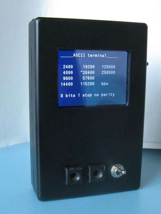
Serial (ascii) monitor with 9 lines of 28 char.
Baudrate from 2400 up to 256000 baud.
Digital 3.3V or 5V input.
Powered by a single Lithium-Ion battery. (3.7V nominal).
Supplies:
ILI9341 display (here a parallel version is used)
BluePill (or other board with a STM32F103C8)
74HC14 (hex invering schmitt trigger)
3.3V low dropout voltage regulator
rotary encoder (with or without button)
lithium ion battery (e.g. from old telephone)
some capacitors and resistors
power switch
project box
PCB (perfboard)
Code can be downloaded here:
https://gitlab.com/WilkoL/serial-monitor
Step 1: Why I Made It.
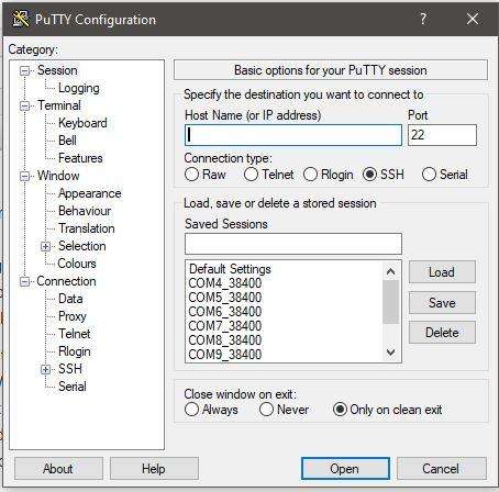
I use it to replace a program on a pc, called Putty, to show debug output of other devices I make with microcontrollers.
Putty is a great little program. It supports several types of connections such as secure shell (SSH), Telnet for connections to old network devices and of course, serial connections that can be used for microcontrollers and other serial devices. I still use Putty often, mostly for managing Linux and sometimes for debugging purposes.
To use the serial connection on a pc you need a USB-Serial converter (real serial ports are very rare on pcs). Unfortunately Microsoft Windows is quite annoying in that it puts the virtual port often on another numbered COM port when you use a different USB port. And every time you use another USB-Serial converter it does that again. So you have to check with the “device-manager” what port Putty should use every time and make another entry in its list of possible connections. Soon you have a long list of COM ports in Putty to choose from.
The other annoyance is that not all devices use the same baudrate (the speed of the data), older devices often use 9600 baud, newer devices can use speeds from 38400 up to 115200 baud and sometimes even higher. Again, in Putty the list of COM ports with the required baudrate increases.
And last but certainly not least, Putty uses some space on my screen. Even though I have a dual screen setup I often have to drag the program to yet another place because of all the things I want to see at the same time.
So that’s why I made this little monitor. It is to display debugging info, so it only has to display a few lines of text. Usually it is a few numbers of variables I want to monitor during the running of the program.
Step 2: Hardware
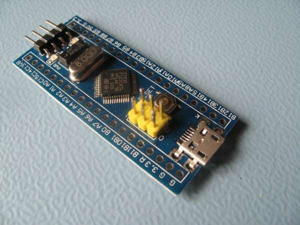
It is made with a STM32F103C8 microcontroller on a Blue Pill development board. The STM32F103C8 is cheap, quite fast and more than capable for a job like this.
The LCD screen is a ILI9341, these a quite common on Aliexpress, Ebay and others, but I made a mistake in buying this particular type. Most ILI9341 use a SPI interface to let the microcontroller control the LCD, SPI needs just three wires.
The one I bought has a parallel interface (8080 ?) meaning it needs 8 wires just for the data and 5 wires for control signals. If you have made the same mistake in buying the parallel version of the ILI9341, take a look at the library I made for it. It is very similar to the SPI libraries so you won’t have to change much in your program to use it. It did take some tuning, such as direct writing to registers to get it to work with enough speed.
Step 3: Working (executive Explanation)
The working in short. The USART receives a character, generates an interrupt that puts the character in a (circular) buffer. The main program constantly checks for new data in this buffer. If there are new characters it puts them on the LCD in the next available place. If the received character is a line-feed or a carriage-return it leaves the rest of the line on the LCD empty and continues on the next line. When it is at the botton of the LCD it starts at the top again. There is no scrolling.
Change the baudrate a rotary encoder is used. It connects to a timer that is configured in the Encoder mode. So it counts the pulses created by the rotary encoder. To get rid of contact-bounce, the inputs are filtered, both with a physical RC-filter and with the digital filtering available in the STM32F103C8. To give the proces of receiving data and putting it on the LCD as much time as possible the rotary encoder is “monitored” by an EXTI interrupt, more on that later. This way the main routine only spends some of its precious time at the rotary encoder when it is actually active.
Step 4: Input
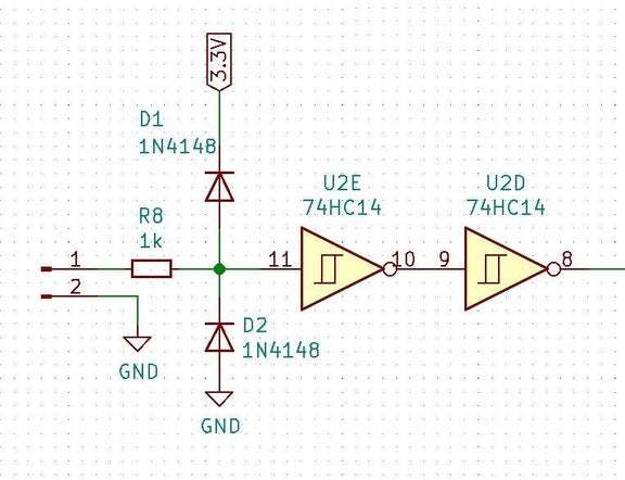
Serial data enters via a resistor of 1k into a 74HC14. There are two protection diodes that clamp the input voltage to the powerrails (GND and 3.3V) so it is 5V safe. The 74HC14 is an inverting schmitt-trigger. The schmitt trigger takes care of removing some noise on the input signal but as a serial signal should not be inverted a second inverter follows the first. The other 4 inverters of the 74HC14 are not used.
The clean, 3.3V high, signal enters the microcontroller on the RX input of the USART. This USART converts the serial data into a (parallel) byte, usually called a char, when this conversion is done it generates an interrupt. The interrupt routine stores the char in a circular buffer. I made this buffer rather big, 4096 bytes long, because there is no handshake that tells the thing that is sending the data to stop when the buffer is full. I tested this setup with large amounts of data on the highest speed of 256000 baud.
Still it does crash when you send it too much. But as this thing is meant to display no more than 9 lines of 28 char (252 characters) in practice it will never be a problem. The whole idea is to be able to READ what is on the screen before it is overwritten by more data, isn’t it?
Step 5: Encoder – Bounce – Timer
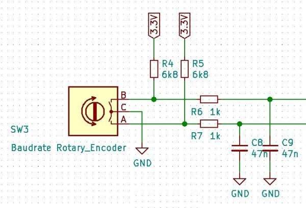
The signals from the rotary encoder first go through a RC filter that I put in with every rotary encoder as a standard. Those cheap encoders suffer from a lot of contact bounce. So they need all the filtering you can get. In the pictures above you can see the effect of the analog filtering. One picture shows the signal that would enter the microcontroller if there was no analog filter. The next picture shows the signal after the filter and inverting schmitt triggers.
The signals are filtered again inside the microcontroller. You can set how long the signal has to be stable before it is recognized as a real high or low level. I have set it to the highest filtering level. Next it goes into a timer (TIM3) that is configurated in a special way. Normally a timer counts a clock signal and acts when it reaches a certain level (e.g. to create a PWM signal) Or it stores the current counter value in a special register when a signal on one of its inputs is activated (e.g. to measure pulsewidths).
Here it is configured in such a way that it “counts” the pulses from the rotary encoder. It increments when rotated in one way and decrements when rotated in the other direction. You can also set the maximum number it will count to, after which it will restart to count from zero. This is a perfect way to connect rotary encoders to a microcontroller, the timer does all the work, you only have to read its content, no other processing is needed.
Step 6: External Interrupt (EXTI)
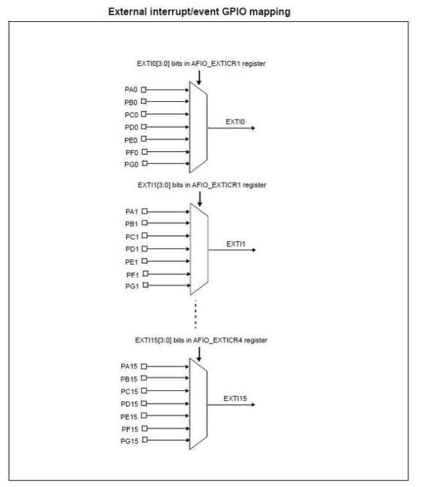
With STM32 microcontrollers is is possible to monitor almost every pin for changes, either rising levels, falling levels, both rising and falling and fixed levels. This is done with the EXTI controller, the External Interrupt controller. It is even possible to monitor pins that are already in use by another device!
In this case the EXTI controller monitors one of the input signals of the timer that is connected to the rotary encoder. When it detects that there is a change in level of this signal (when you turn the knob) it generates an interrupt that sends a signal to the main program to tell it. It has to look at the timer that counts the pulses of this rotary encoder. It also sets a timeout counter to one second. After this one second the main program can continue its normal function of extracting characters frum the buffer and displaying them on the LCD.
During the second the screen is erased and the current baudrate is displayed. So changing the baudrate can be done on-the-fly.
Step 7: ILI9341 to STM32F103C8 (parallel)
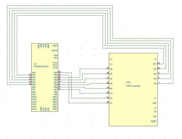
Controlling the ILI9341 was somewhat troublesome because of my mistake to buy the parallel version of it. The manual tells me that you can change it to SPI mode, but that needs to be done in hardware. And as that has been done by the producer of this module and is not accessible by mere mortals like you and me. I was stuck with this parallel mode.
So I needed 8 pins of the microcontroller for the data bus and a further 5 pins for the controlling of it. This number of pins isn’t a problem on a Blue Pill, it is a 48 pin device.
But the “normal” input- output-pins (GPIO) are arranged in groups of 16 pins. You have to send data to a 16 bit register for this port, so you send it to all 16 pins at the same time. When you do this you will send data, not only to the 8 pins connected to the data bus of the LCD, but also to 8 other pins! If you want to use those pins for something else you may have a problem.
But if you use a pin for an “alternate” function, such as the output channel of a timer, that function will *override* the GPIO function of that pin, so the problem only exist for standard GPIO functions.
You can also choose to control all pins separately, but that will slow down the process by a factor of 8 at least. I could not find another way of sending just 8 bits to a GPIO port in one time, if someone knows how to do that, please comment. So I send 16 bit wide words to the GPIO port and simply do not connect the upper 8 pins to anything. The STM32F103 has enough pins left for all the other functions I need here.
Step 8: GPIO PB2
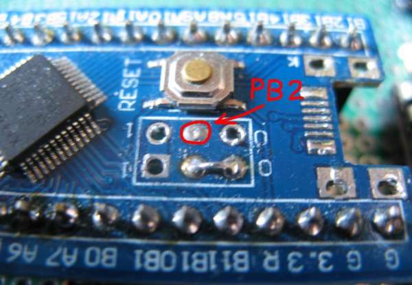
Now, if you take a look at the pins on the Blue Pill board, you will notice that GPIO_PB2 is missing! Iit is available on the STM32F103C8 ! But on the Blue Pill it is used as a BOOT1 pin.
BOOT0 and BOOT1 pins are used to make the microcontroller start in different ways. Most important is BOOT0 which has a pin all for itself, but BOOT1 has to share a pin with GPIO_PB2. I have never used either BOOT0 or BOOT1 so I always remove the jumpers for them and simply connect BOOT0 to ground (meaning start from flash memory).
GPIO_PB2 is now available for other uses although in a strange place on the board, but that doesn’t bother me.
Step 9: Direct Register Access
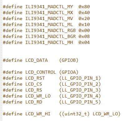
So putting data on the data bus of the LCD was solved, but the ILI9341 also needs control signals such as a Chip Selext (CS), a signal that tells it the data is a command or data (RS) and most important a kind of clock signal that tells the ILI9341 that the data on the bus is valid (WR).
Those signals are very simple to create. Just tell the GPIO to set the pin High or Low with the standard functions in the libraries of STMicroelectronics, speed isn’t that important.
The WR signal on the other hand needs to be fast. You want to put data on the screen as fast as possible. The standard way of the libraries that STMicroelectronics delivers with their microcontrollers (the HAL or the LowLayer libaries) were not fast enough for me.
First I tried to use to write directly to the output register of the GPIO ports (ODR). That was a lot better already, but the fastest way proved to be, set a pin High by directly writing the BSRR register of the GPIO and the BRR register of I to set a pin to Low level. Writing a screen full is now so fast it seems to appear instantly. I like those BSRR and BRR registers.
The library for the ILI9341 was originally written by Sparkfun, Adafruit or other(s), I found it “as is” on the internet, written to use with a SPI connection on an ATMEL ATMEGA328. I ported and adapted it for the STM32 and my parallel ILI9341. So most of the code in it wasn’t created by me, but I have no idea who did. But I thank them for it, reading the manual for an ILI9341 isn’t fun…
Source: Serial Monitor With ILI9341 and BluePill
- What is the primary purpose of this device?
To replace PC programs like Putty for displaying debug output from microcontrollers. - How does the device handle different baudrates?
A rotary encoder connected to a timer allows users to change the baudrate on-the-fly. - Can the input handle 5V signals safely?
Yes, protection diodes clamp the input voltage to the power rails, making it 5V safe. - What interface type was used for the LCD?
A parallel interface (8080 mode) requiring 8 data wires and 5 control signal wires. - How is contact bounce filtered in the rotary encoder?
The design uses both a physical RC-filter and digital filtering within the STM32 microcontroller. - Why were BSRR and BRR registers used?
Standard library functions were too slow; these registers allow faster pin toggling for screen updates. - How is GPIO_PB2 made available on the Blue Pill?
The BOOT1 jumper is removed and BOOT0 is connected to ground to free up the pin. - What happens when the buffer reaches its limit?
The circular buffer wraps around to the top, though sending too much data can still cause crashes. - Does the display support scrolling?
No, when the bottom of the screen is reached, the display starts over at the top without scrolling. - What is the maximum baudrate supported?
The device supports baudrates up to 256000.