In this instructable I want to show you how to control a servo using a microcontroller (18F2550) and how to avoid using an unknown library to control a servo.

Step 1: Materials
- Power supply
- Breadboard
- Wires or jumpers
- Resistors
- Transistor or optocoupler
- Microchip microcontroller
- PICC Compiler(It could be another one, but I’m going to use this one)
- Microcontroller programmer(I use MicroProg R2, but you can use another one)
- Computer
Step 2: Behavior of Position Altering the Signal
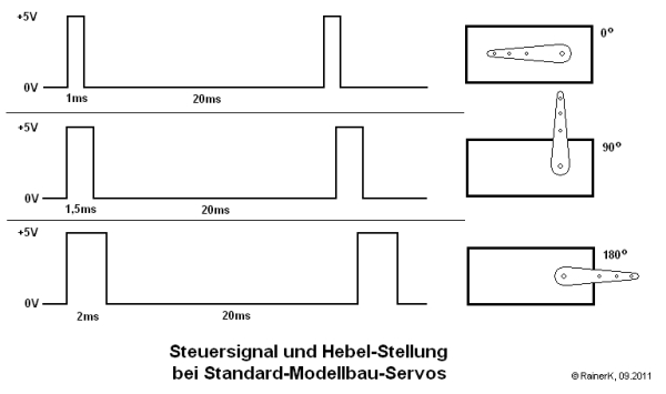
Once you get the material, you need to wire the circuit, but to control a servo you must know how they work, so we check on the internet and get a diagram like the one above, the diagram tells us that the position depends on the pulse width and the max pulse duration is 2±0.2ms and the min duration is 0+0.2ms, so the signal period is 20 ms approximately and it should be sent on a frequency of 50Hz.
Step 3: Transistor Circuit
After knowing how to control a servo you need to design a circuit, for this we need to use different components in this case we are going to use a transistor or optocoupler(For optocoupler skip this step). The transistor that we are going to use in this case is a 2N2222 (Or any other BJT NPN). The main characteristics of this transistor is that amplifies the current and it needs 2 resistors one for Load (R1) and one to activate the transistor (R2). To calculate the resistor you should check this.
Before calculating resistor you must know the max current that the signal can handle so checking again on the internet we find that servo’s signal it’s read by a microcontroller(uC) and that it max current is 20mA. Knowing this we assume a lower current to avoid damage the servo’s internal circuit, the assumed current 10mA. and calculating resistors we find R1 = 1kΩ | R2 = 5kΩ(We look for commercial value 4.7K).
Step 4: Optocoupler Circuit
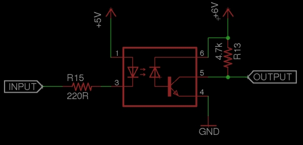
If your plan is going safe optocoupler is a good idea to isolate circuits, in this case could be used to isolate the microcontroller (uC) from being damaged by the servo if its power supply has a short circuit with signal or problems by bad resistor calculations, in this case the optocoupler resistor are calculated in the next way
R15 = (LEDpowersupply – LEDrequiredvoltage)/ LEDrequiredcurrent
The LEDrequiredvoltage and LEDrequiredcurrent can be obtained in optocoupler’s datasheet
Assuming LEDrequiredvoltage = 1.2 and LEDrequiredcurrent = 17mA and LEDpowersupply = 5
R15 = (5 – 1.2) / 17mA
R15 = (3.8) / 17mA
R15 = 223.52(But this kind of resistor isn’t available so we look for a commercial value 220Ω
And for the R13 resistor we make a calculation like a transistor(Check previous step for more info)
Step 5: Build a Simulation Circuit on PC
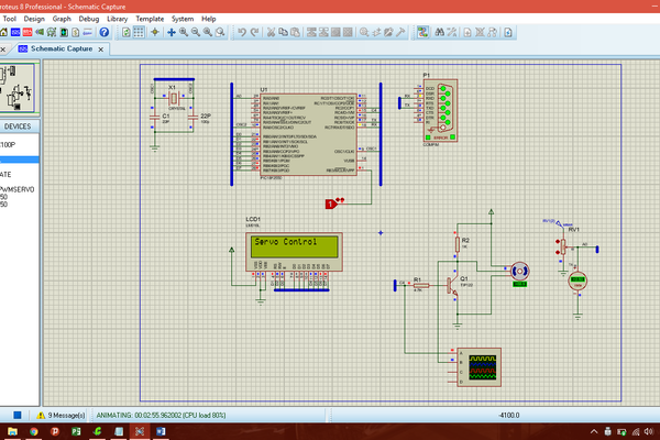
Before testing any circuit I suggest to check your circuit on a simulation software.
I suggest ISIS Proteus but you could use another one that let you run microcontroller’s programs.
Step 6: Writting the Code
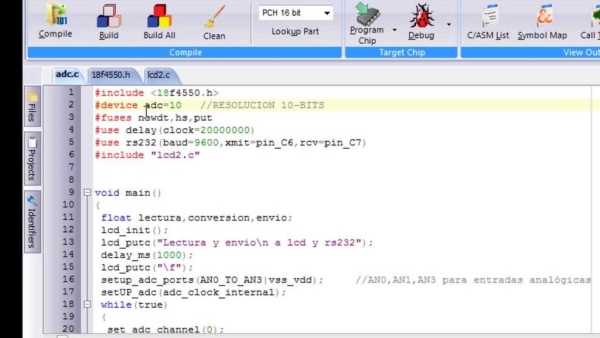
Well I’ll explain inside the code
#include <18F2550.h>      //We indicate that we are going to work with PIC18F2550 and to load its commands
#device    <adc = 10>        //Here we tell to the uC that is going to use its analogic-digital converter with a resolution of 10 bits
#use delay(clock=48M)         //We indicate that the oscillator that we are going to use has a value of 20MHz
#fuses NOWDT,HSPLL,NOLVP,NOPROTECT,NODEBUG,PLL5,CPUDIV1,VREGEN   //We obtain 4MHz frequency with commands and deactivate some options
#use fast_io(C)            //We indicate that we are going to establish Inputs and outputs in the program
#define signal pin_C4         //We indicate signal = pin_C4
#include "LCD.c"            //Used for debug operationsint16 position=0,k_value = 20000;   //Here we declare the variables that we are going to use 						//We use "int16" because "int" vars only reach a value of 255 max
float resolution;                //More variables
void main(){                  //Main loop
lcd_init();
setup_adc_ports(ALL_ANALOG);      //We declare that all the uC pins that have the prefix "AN" are going to be used as analog inputs
setup_adc(ADC_CLOCK_INTERNAL);      //We declare that we are going to use the internal clock of the uC
set_adc_channel(0);           //Change adc port to work in this case AN0
delay_us(20);                 //Stabilization time
set_tris_C(0x00);             //We indicate PORT C as output
resolution = 2000 / 180;      //Cross multiplication to obtain microseconds by degree (2000 microseconds = 2 miliseconds)
printf(lcd_putc,"\fServo Control");
while(true){                  //Start while (Always is going to be running)
position = read_adc();        //We read a value between 0 to 1023
position = 180 - (position * 180.0 / 1023.0);   //We use cross multiplication to convert the first range(0 - 1023) to a new range(0 - 180)
position = position * resolution;               //We make a conversion of position to microseconds(0 - 2000) also obtaining miliseconds (0 - 2)
if(position<=0){              //if(position<=0) start, here we tell to the program that the minimum value is 1 microsecond
position = 1;
}                             //if(position<=0) end
for(int i=0;i<50;i++){        //for start here we tell to the program thar repeat the code 50 times to obtain a 50Hz frequency
output_low(signal);           //Here we send a low pulse
delay_us(position);           //The duration of the low pulse is the same as position
output_high(signal);          //Here we send a high pulse
delay_us(k_value - position); //The duration of the low pulse depends on the difference between k_value and position
}                             //for end
}                             //End while (Always is going to be running)
}                             //End Main Loop
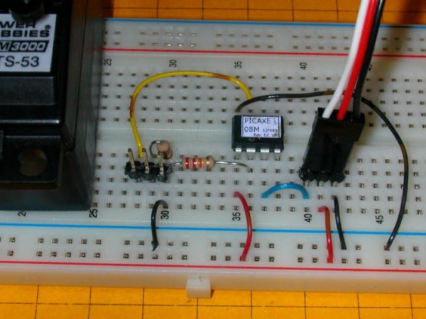
Step 7: Build the Circuit
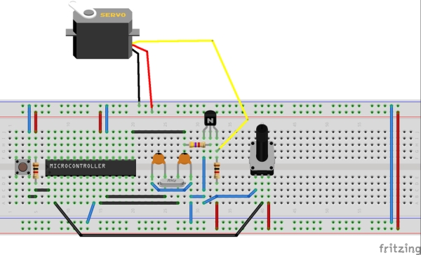
In this case the servo motor and microcontroller works with 5V and the microcontroller used is PIC18F2550 and taking into account manufacturer’s datasheet we make the needed connections.
Step 8: Bibliography & End

This is my first instructable, I know it isn’t good enough an I’ll be working on it, if you have any suggestion to this instructable let me know and comment it below.
Thanks for reading and have a nice day 😉
1.-http://electronics.stackexchange.com/questions/48988/properly-controlling-a-6v-servo-motor-from-a-microcontroller
User: Kit Scuzz
——————————————————————————————————————————————————
2.-http://www.trainelectronics.com/Animation_servos/
User:Dave Bodnar
——————————————————————————————————————————————————
3.-http://www.engineersgarage.com/contribution/expert/servo-motor-control-using-555-timer-ic
User:Ganesh Selvaraj
——————————————————————————————————————————————————
4.-http://www.aaroncake.net/circuits/servocon.asp
User:Think Tank column of the October 1995 issue of Popular Electronics.
——————————————————————————————————————————————————
5.-http://flugleiter.de/wp-content/uploads/Servo-Signal.png
User: Laurens-wuyts
——————————————————————————————————————————————————
6.-https://www.fairchildsemi.com/datasheets/PN/PN2222…
Manufacturer: Fairchild Semiconductors’
2N2222A Datasheet
——————————————————————————————————————————————————
6.-http://ww1.microchip.com/downloads/en/DeviceDoc/39…
Manufacturer: Microchip
18F2550 Full Datasheet
Source: Servo Control With Microchip Microcontroller