
Summary of Servo motor control using Atmega8 microcontroller
This article explains that servo motors are closed-loop systems using a control circuit, gears, and a potentiometer to achieve precise positioning. They operate on DC voltage (4.8–7.2V) and are controlled via pulse width modulation (PWM) signals sent through three wires: power, ground, and control. The system adjusts motor speed based on the error between current and desired angles, making them ideal for robotics and remote-controlled applications.
Parts used in the Servo Motor Project:
- Motor
- Gears
- Motor driving circuit
- Control circuit
- Potentiometer
- Digital controller
- Power source (DC 4.8 to 7.2V)
- Three wires (Power, Ground, Control)
- Microcontroller or computer
Servo motors are so called “closed feedback” systems. This means that motor comes with control circuit, which senses if motor mechanism is in desired location and if not it continuously corrects an error until motor reaches proper point.
Servo motors are widely used in robotics, remote controlled planes, vehicles. So they come in many shapes and sizes, but they operate in almost the same way. Usually Servo motors are controlled by computer, microcontroller or even simple timer circuit. Of course you may find more advanced servos – R/C so called radio controlled. But again, they are same servos just it takes signals from receiver.
How Servo Motor Control Works
Usually servo motors are put in plastic box, but inside there is a whole system: motor itself, gears and motor driving and control circuit.
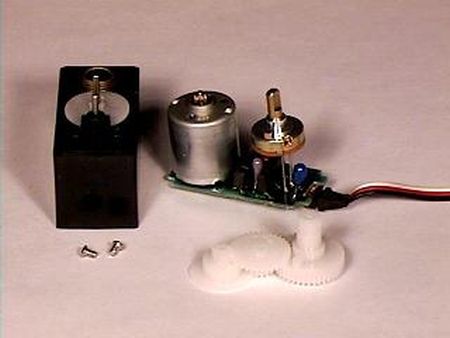
the gears reduces motor speed but increases torque. As we mentioned that servos works with closed feedback loop. This is actually potentiometer which is connected to mechanical shaft and senses the angle of turn. So potentiometer voltage directly indicate the angle of turn. Potentiometer signal goes to digital controller of motor which powers motor until potentiometer reaches desired angle, then logic shuts the motor.
Servos usually are powered by DC voltage from 4.8 to 7.2V.
Usually servos are designed with limited rotation angle like 90° or 180° and so on. Of course they can be modifier for continuous rotation. Precise rotation and force thanks to gear system servos are ideal for robotic purposes.
Servo control signals
Servo motor shaft is positioned with pulse width modulated signals. So all servos comes with three wires (Power, Ground and Control). So pulses are sent via control wire. Usually in hobby servos with rotation angle 90° signal width vary between 1 and 2ms. If pulse is more wide rotation continues until reaches mechanical limits.
The frequency of PWM usually is in range from 30 to 60Hz – this is so called refresh rate. If this refresh rate is too small then then accuracy of servo reduces as it starts lose its position periodically if rate is too big, then servo can start chatter. It is important to select optimal rate, that servo motor could lock its position.
The motor powering circuit power motor depending on what is difference between current position and where it should be. If this difference is small the energy portion given to motos is small that it wouldn’t overshoot the position – motor in this situation is driven slowly. But is difference is big, then motor is powered to turn at full speed that it could reach new position as fast as possible. When shaft approaches to new position, at he end of movement motor slows down in order to stop at accurate position. This complicated process lasts for about a half a second when rotation angle is 60°.
For more detail: Servo motor control using Atmega8 microcontroller
- How does a servo motor correct its position?
The control circuit senses the location via a potentiometer and continuously corrects errors until the motor reaches the desired point. - What is the function of the gears in a servo motor?
The gears reduce motor speed but increase torque. - Does the potentiometer signal go directly to the digital controller?
Yes, the potentiometer signal goes to the digital controller which powers the motor until the desired angle is reached. - What is the typical DC voltage range for powering servos?
Servos are usually powered by DC voltage from 4.8 to 7.2V. - Can standard hobby servos be modified for continuous rotation?
Yes, although they are designed with limited rotation angles like 90° or 180°, they can be modified for continuous rotation. - How does pulse width affect servo rotation?
In hobby servos, signal width varies between 1 and 2ms; if the pulse is wider, rotation continues until it reaches mechanical limits. - What happens if the PWM refresh rate is too small?
If the refresh rate is too small, accuracy reduces as the servo starts losing its position periodically. - How does the motor speed change based on position difference?
If the difference is small, energy given is small to prevent overshooting; if big, the motor turns at full speed to reach the new position quickly. - What is the typical time required for a 60° rotation?
The complicated process of moving and stopping lasts for about a half a second when the rotation angle is 60°.
