Summary of Simple LED Projects Using AVR Microcontroller
This article demonstrates three simple LED projects using the ATmega328 AVR microcontroller to teach basic concepts: blinking two LEDs, controlling two LEDs with a push button, and toggling two LEDs with a push button. It explains required tools (Atmel Studio), wiring (LEDs on PB2 and PB3), key code elements (F_CPU, avr/io.h, util/delay.h), DDRx and PORTx usage, and using _delay_ms(1000) for one-second timing. The examples show how to set pins as outputs and drive them high or low to create blinking and button-controlled behaviors.
Parts used in the ATmega328 LED Projects:
- ATmega328 microcontroller
- Two LEDs
- Resistors for LEDs
- Push button switch
- Wiring/jumper wires
- Power supply (matching F_CPU configuration, e.g., 1 MHz clock source)
- Breadboard or PCB for assembly
- Computer with Atmel Studio 7
This article is another step forward in learning more about AVR microcontrollers. We have demonstrated 3 simple LED based projects using ATmega328 microcontroller, which will help you to learn its basic concepts. ATmega328 is an eight bit AVR (Advanced Virtual RISC) based microcontroller. It is a powerful microcontroller with a built-in internal memory of around 32Kb. Most Arduino boards consist of an Atmel 8-bit AVR microcontroller with varying amounts of flash memory, pins, and features. Arduino Uno is a microcontroller board based on the ATmega328.
AVR microcontrollers are very easy to use. All AVR microcontrollers require Integrated Development Environment(IDE) such as Atmel Studio. Using this IDE, we can create, compile and debug program on all AVR microcontrollers.
Let’s develop simple LED Blinking programs for ATmega328 using Atmel Studio 7.
- Blinking Two LED’s using ATmega328
- Control Two LED’s using a Push button switch
- Toggle Two LED’s using a Push button switch
#1. Blinking Two LED’s using ATmega328
In this section, we will learn How to blink two LEDs with AVR ATmega328 microcontroller. First, we will connect the 2 LED’s with PB2 and PB3 of PORTB of the ATmega328 microcontroller. Then, we will make the 2 LED’s to blink with an interval of 1 second. It means, initially the 1st LED alone will glow and on the next second, it will turn off and the 2nd one will glow. This process continues forever and in this way LEDs blinks continuously.
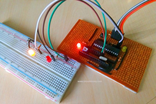
Assemble the circuit as shown in diagram. A photograph of the assembled circuit is shown below. A video demonstration of the project is shown below.
Program Explanation
Blinking Two LED’s Using ATmega328 – Download Program
At the beginning of the program a pre-processor named “F_CPU” is defined. It is simply your way to tell some of the library code how many CPU cycles per second the processor is executing. Here we defined the F_CPU as 1 MHz. “#include <avr/io.h>” is a header files which provides you with various i/o operations like DDRx, PINx, PORTx, etc. “#include <util/delay.h>” is a header file which provides you with inbuilt delay functions like _delay_ms(), _delay_us(), etc. “_delay_ms(1000)” provides a delay of 1000 milliseconds (i.e., equivalent to 1 second).
DDRx – Data Direction Register configures data direction of the port(Input/Output). The instruction “ DDRB |= (1<<DDB2)” makes corresponding port pin as output.

PORTx – Port register is for assigning appropriate values for the port pins.
Writing to PORTx.n will immediately change state of the port pins according to given value. “PORTB |=(1<<PORTB2)” will generate a high signal at PB2. And “PORTB&=~(1<<PORTB3)” is for generating a low signal at PB3.
Read more: Simple LED Projects Using AVR Microcontroller
- What projects are demonstrated using the ATmega328?
Blinking two LEDs, controlling two LEDs with a push button, and toggling two LEDs with a push button. - Which pins are used for the two LEDs?
PB2 and PB3 of PORTB are used for the two LEDs. - What IDE is required to program the AVR microcontroller?
Atmel Studio is required to create, compile, and debug programs for AVR microcontrollers. - What does F_CPU define do in the program?
F_CPU tells library code how many CPU cycles per second the processor executes; in the article it is defined as 1 MHz. - Which header files are used in the example code?
The code uses avr/io.h and util/delay.h header files. - How is a one second delay achieved in the code?
Using _delay_ms(1000) provides a delay of 1000 milliseconds, equivalent to one second. - How do you set a port pin as an output?
By setting the corresponding DDRx bit, for example DDRB |= (1<<DDB2) makes PB2 an output. - How do you drive a port pin high or low?
Use PORTx operations: PORTB |= (1<<PORTB2) sets PB2 high; PORTB &=~(1<<PORTB3) sets PB3 low.