Summary of Sinewave and Cosinewave Signal Generator
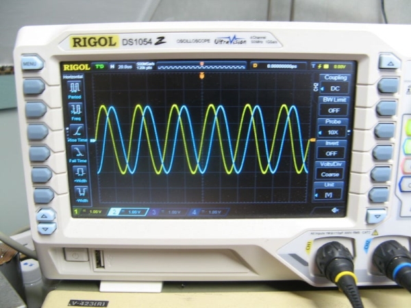
This project implements a DIY sine and cosine signal generator using Direct Digital Synthesis on an STM32F407 dev board, with external op-amps, ±5V power rails, relay-switched attenuator, and an LCD. It uses DMA-driven DAC output at up to 7 MHz reference ticks, a rotary encoder UI, and output buffering for amplitude/offset control; hardware and software optimizations and limitations are discussed.
Parts used in the Signal Generator:
- STM32F407VGT development board
- LMH6645 opamps (2 pcs) or equivalent
- LMH6643 dual opamp
- Rotary encoder with switch
- 4 MHz crystal oscillator (external)
- BC547 or equivalent NPN transistors (4 pcs)
- LM7805 linear regulator
- LM7905 linear regulator
- LP2950-3.3 linear regulator
- Transformer 240V / 7.5V (or appropriate for your mains)
- Small signal relays (e.g., OMRON G6S-2 4.5V)
- LCD ST7735 (SPI)
- Perf-board (100mm x 150mm)
- Assorted resistors and capacitors (see schematic)
- Handful of wiring and connectors
- STLink-V2 or Segger J-Link programmer/debugger
- PC with STM32IDE, STM32CubeMX (or equivalent tools)
- Miscellaneous hardware: aluminium project box, trimmer potentiometer (10k, 10-turn)
For an upcoming project I need a signal generator that produces a sine wave and a cosine wave*. The easiest way would be to buy a signal generator. I also could buy one of those amazing integrated circuits that Analog Devices makes and build a generator with that, but where is the fun in those options?
So I build one.
* (A cosine is just a sine wave shifted 90 degrees in phase.)
EDIT! I changed the schematic, take a look at new_schematic in step “The Hardware”
Supplies:
1 x STM32F407VGT development board (Ebay)
2 x LMH6645 Opamps or equivalent (Mouser, TME)
1 x LMH6643 (Dual) Opamps (Mouse, TME)
1 x Rotary Encoder + Switch (Ebay)
1 x 4 MHz crystal oscillator (Mouser, TME)
4 x NPN transistors, BC547 or equivalent (Mouser, TME)
1 x LM7805, LM7905 and LP2950-3.3 (Mouser, TME)
1 x Transformer 240V / 7.5V (or what is needed in your country)
1 x Small signal relays e.g. OMRON G6S-2 4.5V (Ebay)
1 x LCD ST7735 (Ebay)
1 x perf-board 100mm x 150mm (don’t remember where it came from)
handful or resistors and capacitors (see schematic)
PC with Linux, Windows or Apple
STM32IDE, STM32CubeMX, Notepad++ and what else you want
STLink-V2 or Segger J-Link
The STM32F407 datasheet
RM0090, the reference manual of the STM32F407
AN4013 cross reference timer overview
AN4031 using DMA in STM32F2.4.7
AN4566 extending DAC performance
much coffee and a lot of time
Step 1: Direct Digital Synthesis
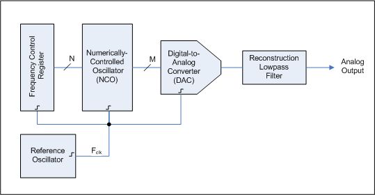
The usual way to generate a waveform with a micro controller is to use an algorithm called Direct Digital Synthesis (DDS) and that is what is used here. I’ll try to explain how it works.
(https://en.wikipedia.org/wiki/Direct_digital_synthesis)
Don’t let the name scare you off, once you see how it works it is simple.
(picture stolen from Wikipedia)
Step 2: DDS Explained
You can skip this Step if you are not interested in how DDS works, or if you already know.
The basis is a table with the values of a sine wave, (see the picture). To produce the signal you need to take those values and feed them in the DAC. Shown in the table are 32 values (in the program for the micro controller we’ll use more)
We need a counter to select te wanted value from the table, a so called phase counter, let us use one counting from 0 to 65,535 (16 bits). This counter is coupled to the values in the table but after dividing the number by 2048. So to go from one value in the table to the next the counter needs to be increment by 2048.
(All numbers we use are integers, that means that there are no fractions, so 12/5=2 but also 2047/2048=0 2048/2048=1 2049/2048=1 and so on.)
Next we use a timer to increment this phase-counter let’s take a timer that does this 1,000,000 times per second (1 MHz). At each tick of this timer we increment the phase_counter with a certain step size e.g. 1 or 13 or 3465. Let’s keep it at 1. So after 1,000,000 / 65,536 ticks we have completed 1 full sine wave and we can do that 15 times in a second. That’s a sine wave with a frequency of 15 Hz. A rather low frequency.
Also remember that we divided the phase-counter by 2048 to select a value from the table, this means that each value was sent 2048 times to the DAC before we jumped to the next value. Let’s see what happens if we increase the step size from 1 to 16.
We now need just 65,536 / 16 = 4096 ticks to make a full sine wave, that is done in 1,000,000 / 4096 = 244 times a second, 244 Hz. Each value from the table now is send just 128 times to that DAC before the next one is selected.
So the step size determines the output frequency, and the formula to find this step size for a wanted frequency is this:
step size = frequency * 65,536 / 1,000,000
As a check, we want 1000 Hz: step size = 1000 * 65,536 / 1,000,000 = 65 (remember no fractions!) To go from 0 to 65,536 with increments of 65 we need 1008 ticks. We do 1,000,000 ticks per second so that can be done 1,000,000 / 1008 = 991 times per second. Not quite 1000 Hz but close enough. And still we send out each value 31 times before the next one.
How about 100 kHz? The step size = 100,000 * 65536 / 1,000,000 = 6553. We now race through the table in 10 steps, that means that of the 32 values in it only 10 are used, that will make the sine wave a lot less like a real sine wave.
So for high frequencies we will start to skip values in the sine wave table. That will produce a more distorted sine wave at the output of the DAC so we cannot go too far with that. Nyquist-Shannon may say that 2 values are enough for a sine wave, I think 7 or 8 values is a reasonable lower limit.
(https://en.wikipedia.org/wiki/Nyquist%E2%80%93Shannon_sampling_theorem)
Step 3: Some Real Numbers
In the signal generator described here, the reference frequency is 7 MHz, the sine wave-table has values numbered from 0 to 1023 and the counter runs from 0 to 4,294,967,295.
So the counter goes all the way from 0 to 4,294,967,295 and the sine wave values are numbered from 0 to 1023 we need to divide the counter by 4,194,304 to be able to get 1024 values from the table.
As said the counter is incremented 7,000,000 times per second (the reference) so if we increment the counter by 1 each time it will take 4,294,967,295 / 7,000,000 = 613 seconds to go one round trip. And in these two minutes! each value of the sine wave table will be send to the DAC 4,194,304 times.
One cycle per 2 minutes, that’s a very low frequency of 1.63 milli-Hertz. Not very useful unless you do seismographic work. If instead we increment the counter each time with a higher number, lets take a step size of 1000, we get 1.63 Hz, ah that’s better. With a step size of 613,566 the output frequency is 1000 Hz. That’s more like it.
Let’s go to 500 kHz, the step size is 500 * 613,566 = 306,783,378
But now it takes just 14 steps of the counter to go from 0 to 4,294,967,295 this means that there are just 14 values taken from the sine wave table to construct the sine wave at the DAC. As I think that 7 or 8 is the lower limit this fixes the maximum output frequency of the generator to around 1 MHz. Good enough for me, and as it turns out, also at the limit of the capabilities of the STM32F407.
So the value of the step size defines the output frequency via this formula:
step size = (frequency * 4294967296) / reference
As you see the numbers in this calculation get very big, so we need to use 64 bit variables. In the program I use even bigger numbers because I do not want to use floating point variables. I multiply both the frequency and the reference by 100 to be able to work with frequencies with 2 decimal digits.
I hope this explains the workings of a DDS.
Step 4: The Hardware
The hardware
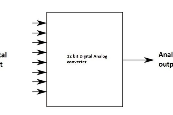
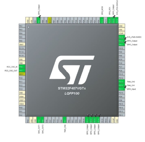
I decided to use a small development board with a STM32F407VGT, available on Ebay (and others) for less than 8 euro. This microcontroller has two Digital-Analog-Converters (DAC) and it can run at 168MHz. So it is cheap and fast, I like that.
Because the output of a microcontroller working on +3.3V is always positive and I want the signal to go positive as well as negative I also need two opamps to shift the signal down in voltage. To give the opamps a bit room for the outputs I decided to supply them with +5V and -5V.
So the powersupply has to deliver three voltages. It is also nice to be able to change the amplitude of the waves, one here with an attentuator made with four small signal relays in 16 steps of 3dB, from 0dB to -45dB.
The STM32F407 development board is cheap and that means they had to use less quality components. Most important here is the *stability* of the crystal oscillator. It turns out that it isn’t a crystal at all that is soldered on the board but a ceramic resonator. It should resonate at 8 MHz but the one I got actually worked at 7,936 MHz
This isn’t in itself a problem, I can adjust the value of the reference in the program to the actual frequency but the ceramic resonator is very sensitive for variations in temperature. So I chose to use an external crystal oscillator and removed the ceramic resonator (and 2 capacitors next to it) from the board.
The power supply: Mains voltage is brought down with a transformer of 7.5V eff, two diodes rectify the positive and negative phase and the rest is all the usual stuff, 2200uF capacitors, a 7805 and a 7905 for the +5v and -5V. I wasn’t to sure that the 3.3V linear regulator on the development board could supply enough current for what I had in mind so I took that off the board as well and used a LP2950-3v3 instead. In the end that probably wasn’t needed.
The opamps are LMH6645’s with a BW of 55 MHz (Texas Instuments), the offset voltage for them is generated with a pulse width signal coming from one of the many timers in the STM32F407.
A nice trick to increase the bandwidth of the DAC is to disable the internal buffer of the DAC and use the output *current* of the DAC to feed the opamp-amplifier. It is explained very well in application note AN4566 by STMicroElectronics.
The LCD display is a ST7735 controlled via SPI. The library for it was made by adapting a library from Olexandr Davydenko (https://github.com/o-m-d) who in turn build it standing on the shoulders of Dmitry LonelyWolf (https://github.com/LonelyWolf/stm32). The ST7735 is a colour display, but I use just two colours of it, white and blue. It is simply a small display I had lying around. To get it in the project box it wasn’t small enough, I had to cut off part of it and remove the SD-card socket.
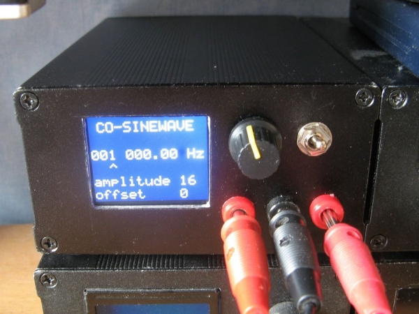
Frequency, amplitude and offset is controlled with one rotary encoder, that is another consequence of wanting to build it in a rather small aluminium project box. But it works quite well. When you have more space on the frontpanel an extra rotary encoder for the amplitude would be nice.
The last thing to mention is the attenuator. It uses 4 small signal relays that switch in or out part of a logarithmic attentuator. (http://www.eijndhoven.net/jos/attenuator-calculator/index.html) You can go in sixteen 3dB steps from 0dB to -45dB. The impedance of the attenuator is 1k ohm. The original idea was to put a buffer between the attenuator and the output of the generator to lower the impedance to the usual 50 ohm but I don’t think I’ll do that, I like the output and the impedance as it is now.
It is all build on perfboard, no printed circuit was designed as I need just one signal generator.
EDIT: It turns out that I did not like it that the offset changed with the attenuator. So It did build the buffer. In the new_schematic it is added to the signal generator. The pwm-generated offset voltage is now rerouted to the output buffers and the offset for the first opamps (amplifier) is made with a 10 turn, 10k trimmer.
The pin numbers for the LMH6643 are wrong, it is a dual opamp, I couldn’t find the right layout in Kicad, check it before you start soldering.
Step 5: Pictures of Building and Testing
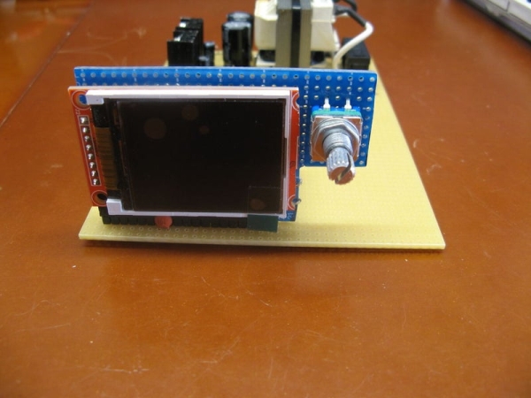
I always forget to make pictures during the build, this is the rest of what I have. Notice that I needed to cut of part of the LCD to make it fit in the project box.
Step 6: The Code
INIT
As I was trying to get the most performance from the micro controller I discovered CCMRAM, core coupled memory. This memory is directly coupled to the processing core and could be used to speed up execution of your code. Unfortunately in the STM32F4 series it is only coupled to the D-bus. This means you cannot use it for code. And even more unfortunate, it cannot be used by the DMA controller! But I had changed things in the linker script to use this CCMRAM so I needed to tell the linker not to put the dac-buffers in CCMRAM, but in normal RAM. If you do not change the linker scripts, leave out the __attribute__((section(“ram”))). It didn’t speed up anything anyway.
From the line
uint32_t const reference = 699994750; //~7 MHz
you can tell that the crystal oscillator does not generate the exact 4 MHz that it should, it actually is 3999970 Hz, thirty Hz too low. That doesn’t matter, the reference is adjusted accordingly.
To transport the data from the arrays to the DAC, DMA is used. Here the STM32F407 DMA shines, you can make it use double buffer mode. That means that while the DMA is busy sending the contents of one buffer to the DAC, the processor can work on the other buffer, undisturbed. In the DMA-IRQ routine we’ll see how this is done.
Timer3 has Channel4 connected to GPIOB_1 port to generate a PWM signal that is used to make the offset voltage for the opamps.
Timer4 is connected to the Rotary Encoder, as I’m only interested in whether it is turned up of down, the actual value of the counter is set to 100, if it is higher than 100 it is turned up, if lower it is turned down. After registrating this, the counter is again reset too 100.
Timer7 is responsible for the timeout after you stop using the Rotary Encoder.
Timer8 is the most important one, it generates the ticks for the DMA, at each tick the DMA has to send the next value in one of its buffers to the DAC. Experimentally I have found that the maximum speed at which this still works reliably is 7 MHz. If you go higher the first thing you will notice is that the output signal isn’t stable when you use the Rotary Encoder, and if you go even higher the DAC starts to skip values send to it. ST claims in application note AN4566 that it should be possible to get the DAC to accept data at a rate of 10.5 MHz (when the micro controller runs at 168MHz) but I could not get it higher than this 7MHz.
Source: Sinewave and Cosinewave Signal Generator
- How does the generator produce sine and cosine waves?
It uses Direct Digital Synthesis (DDS): a phase accumulator indexes a sine lookup table and the values are sent to the microcontroller DACs via DMA. - Can the STM32F407 handle the required update rate?
Yes, experimentally it reliably handles a DMA-driven DAC update tick rate up to about 7 MHz on the STM32F407 at 168 MHz core clock. - What determines the output frequency in the DDS implementation?
The step size added to the 32-bit phase counter each reference tick determines the output frequency via step size = frequency * 4294967296 / reference. - Does the design need negative supply voltages?
Yes, opamps are supplied with +5V and -5V to allow the DAC-referenced signals to swing positive and negative. - What is used to generate the DC offset for the opamps?
An STM32 timer produces a PWM-based offset voltage; in the revised design the offset for the amplifiers is set with a 10-turn 10k trimmer and PWM offset is rerouted to the output buffers. - How is amplitude controlled?
Amplitude is adjusted with a relay-switched logarithmic attenuator using four relays for sixteen 3 dB steps from 0 dB to -45 dB; amplitude can also be adjusted in software via the rotary encoder. - Does the project use the on-board clock crystal?
No, the on-board ceramic resonator was removed because it was unstable; an external crystal oscillator is used and the software reference constant is adjusted to its measured frequency. - What output impedance does the generator present?
The attenuator and output as built present about 1 kΩ; a buffer to 50 Ω was considered and later added to prevent offset changes with attenuation. - Can the DAC internal buffer be used to improve bandwidth?
The design disables the DAC internal buffer and uses the DAC output current feeding the opamp, following application note AN4566, to increase effective bandwidth.