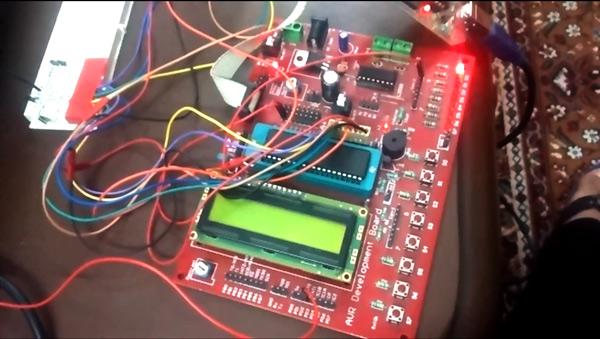
Summary of Sleeping Security – Smart Keypad Lock using AtMega16
This project implements a smart keypad lock using an ATmega16 that enters sleep mode when not needed to save power. It wakes via an external interrupt triggered by diode-OR wiring on keypad presses, resumes execution without data loss, supports changing and erasing the stored password, masks input during unlocking, shows plaintext when setting a new password, and uses an LED to indicate locked/unlocked status. Keypad on PORTC; 4-bit LCD on PORTB; custom keypad header file used.
Parts used in the Smart Keypad Lock:
- ATmega16 microcontroller
- 4x4 Keypad (connected to PORTC)
- 16x2 LCD display (operated in 4-bit mode on PORTB)
- Four diodes (wired as OR for keypad press detection)
- External interrupt line INT0
- LED indicator (for locked/unlocked status)
- Resistors (for LED and keypad pull-ups as required)
- Power supply (suitable for ATmega16)
- Custom keypad header file (software)
This project is just a smart version of any keypad lock. What’s smart about it is that it can detect whether it is needed by the user or not and accordingly switches itself to take a sleep. Making a microcontroller to sleep reduces power consumption as well as increases its usage span.
Many of you must be wondering that would it be secure enough to make a lock go to sleep, isn’t it. Don’t worry, when a microcontroller goes off to sleep it puts a hold on what it was doing before sleeping. In my project I have made it to sleep only when the user has finished entering the password stuff and microcontroller has done its entire job.
This was really necessary because I didn’t find it logical to make the microcontroller keep active all the time even when it’s not needed.
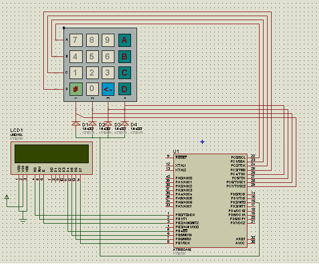
So after entering the sleep mode it can be woken up by any interrupt source. Here what I have done is that I have used 4 diodes in such a way that when any of the keypad buttons is pressed they generate a low level pulse at the external interrupt INT0. INT0 is set to call its ISR routine function when such a thing happens. In short these diodes are working as an OR gate to detect any key pressed.
After waking up, the microcontroller resumes from the position where it went to sleep, thus no risk of data mishandling.
For further references you can see the coding part as well.
The Keypad is connected to PORTC and the LCD works on 4-bit mode with PORTB.
I have used a self-made header file for the keypad interfacing which you can find in this folder itself.
A great thing about this lock is that it can remember your changed password. Now the question that arises is how to change the password? It can be done when the safe is open; you just need to enter the new password that you want. Note this password won’t be hidden, as it is at the unlocking time.
What I want to say is that at the time of unlocking the LCD screen displays “*” for each time user presses a button. This is done to secure the password. But at the time of renewing it, LCD displays the same character pressed on the keypad just to ensure user about the password. Once the password has been changed everything becomes hidden again.
One more feature about this lock that would excite some of you is that you can even erase and rewrite your password. For erasing purposes, “<-” this button needs to be pressed.
In my project I have used a LED as an indication about the lock status. When LED lights up it means unlocked status and when LED switches off it indicates the locked status.
For more detail: Sleeping Security – Smart Keypad Lock using AtMega16
- How does the lock save power?
The microcontroller is put into sleep mode when not needed, reducing power consumption. - How is the microcontroller woken up?
Keypad presses generate a low level pulse on external interrupt INT0 via four diodes wired as an OR, which triggers the ISR to wake the MCU. - Does the lock lose data when it sleeps?
No, when the microcontroller wakes it resumes from where it went to sleep, so there is no risk of data mishandling. - How is the keypad connected?
The keypad is connected to PORTC of the ATmega16. - How is the LCD connected and operated?
The LCD works in 4-bit mode and is connected to PORTB. - Can the password be changed?
Yes, the lock can remember a changed password; changing is done when the safe is open by entering the new password. - Is the password visible when changing it?
Yes, during password renewal the LCD displays the actual characters; during unlocking the LCD displays asterisk characters for each key press. - Can the password be erased or edited?
Yes, the project supports erasing and rewriting the password; pressing the <- button erases. - How is lock status indicated?
An LED indicates status: lit means unlocked, off means locked.