In this indestructible I will demonstrate how to make your Own Solar power Monitoring station .With materials ,Code and electronics parts. we will start with the PCB designed on a fritzing program to sending off for the PCB ,Soldering it and Installing it into a junction Box , then we will Build the solar Junction Box and install the components and power up everything ,Run some simple code and start monitoring.
Links…
www.particle.io (Particle Devices , Console and ide )
www.penteon.io (Particle Power Shield with monitoring capability )
Step 1: PCB Design
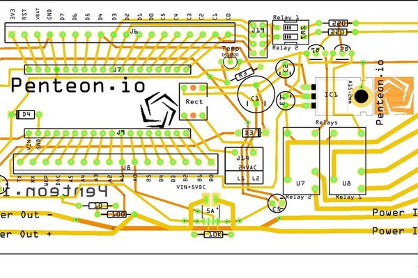
The Program I used is called Fritizing ..Http://www.fritzing.org you can download and install a PCB design program which is free to use ..You can even order the PCB’s directly from the program if you wish or export it as a gerber file for any PCB manufacturer depending on where you live. I went for a company called PCBWay.(PCBWay.com) they are an excellent company who manufacture any PCB you can design ..The turn around from Ordering to delivery into the heart of Canada was 6 days ..Cool huh
The design was simple ..I wanted to be able to power the board with either 18-30 Volts AC or 12-30 Volts DC ..I wanted screw terminals because these are going to be deployed all over the place and I need a perminant solution …
I added a temperature sensor , Current sensor , and a voltage divider circuit to monitor the Solar output and battery state ,and 2 relays controlled by the Micro Controllers through an NPN transistor.
I used a microcontroller called a Particle ..http://particle.io ..These are a great DIY device with Wifi or if you wish cellular connectivity
The electronic parts I purchased from digikey ..www.digikey.ca or www.digikey.com ..They are a parts wholesaler with everything you would need
Step 2: Soldering the PCB
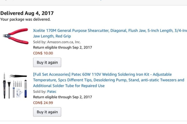
Here is a soldering tutorial. For many soldering is scary and a real challenge and I hope this helps for todos you will need
1. A good soldering iron 60 Watts is plenty…Amazon.ca or Amazon.com is a good start
2. No Clean solder smaller the solder the easier it is to work with
3. A good set of cutters ..Amazon.ca or Amazon.com
4. PCB holder is handy but not necessary
5. Flux(cleaning agent for soldering tiny parts or non through hole pieces (I will demonstrate)
6. Wet sponge
7. Steady hand
Ok now if your ready have all your parts on hand ..Start from the inside to the outside ..Going slowly and methodically insert the pieces and solder them one by one.
I found it handy to have the soldering iron hot and ready to go ..Just touch the board and the piece to be soldered momentarily and add a little bit of solder to the piece and the iron at the same time ..it takes a bit of practice but once you get it ..it’s easy.
Follow the pictures I’ll post them in order..Hope it helps
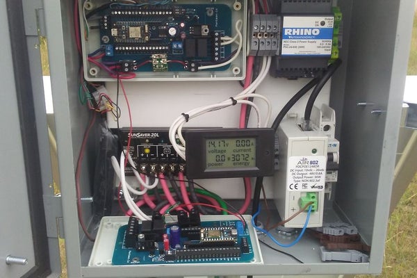
Step 3: Junction Box Design and Integration of the Parts
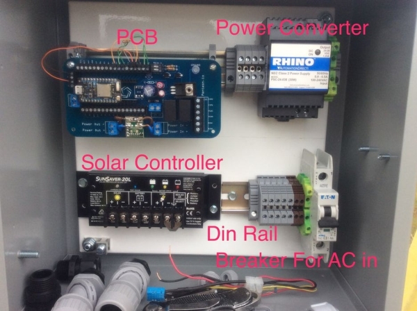
For building an effective junction Box lay out all your Materials and equipment and place everything on the back box ensuring you have enough space for everything.
You will need
1. Battery operated Drill
2. Hex head self tapping screws 3/4″
3.Hex head driver
4.Hacksaw for cutting (din rail )
5.Step bit for drilling holes on the bottom of the box
6.Safety glasses and Gloves (You are working with sharp tools and flying debris…Better to be safe than blind and bleeding )
Most hardware stores have everything you need for the install..Most electrical supply stores have everything else.
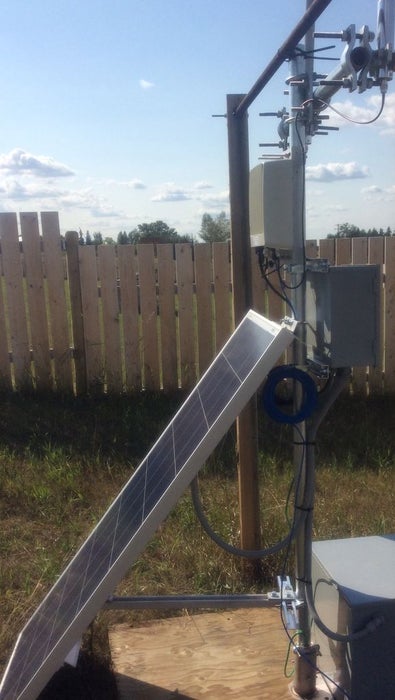
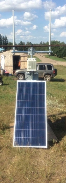
Step 4: Building Your Solar Array
Your Going to need some things
1.Solar Panel..
you can source what size of panel you need by researching what the Watts of the Device or devices you are powering ..Rule of thumb ..ie 60 Watt light bulb x 12 hours a day =720 watt hours of battery usage x 4 days backup ..1200 Watt solar panel 4×12 Volt 100Ah batteries should suffice
2. …
the battery is what you are going to power you systems when its dark so you need to size it accordingly I recommend at least 4 days usage without sun ..you never want to completely drain your battery ..it will cause wear and tear and you will end up replacing it sooner than later ie ..30 watt hours x 4 days = 1200 watt hours of battery’s .
3. Charge controller ..
The Charge controller must be sized for charging amps and panel voltage ..If you need help there are many resources ..A typical Solar 12 volt solar panel will put out about 30 Volts DC in direct sunlight..
NOTE..The Solar panel will immediately produce voltage in sunlight or daylight so care is needed
Links for sizing your Solar system
https://www.wholesalesolar.com/solar-information/s…
4. Wiring ..You should size your wiring to handle the load of your System ..#14 is NOT good for 30 amps #10 is good for 30 amps..I recommend at least #10 30 Amp rated wiring from your panels to the charge controller and Battery
5.Protecting your wiring …
I recommend a flexible non metalic conduit and connectors to interconnect you devices (NEVER JUST RUN THE WIRES OPEN AIR) it will wear eventually and sun and rain will cause degradation .
Step 5: Powering Up the Solar Array and Voltage Measurement
Step 6: The CODE , MONITORING and Alarms

For the monitoring and alarms I used ….
1. Librato Monitoring (https://www.librato.com) 1 month trial free
2.Particle IDE (Http://www.particle.io) free
3.Twillio (https://www.twilio.com) free trail SMS service
Particle IDE Code
https://go.particle.io/shared_apps/59987fc6d2c136f…
Particle Web Hook Above in notepad file
Source: Solar Power System Monitoring