SensCap is a device that guides the visually impaired around obstacles.
Introduction
We designed and built a device to be worn on the head and around the hip to aid the visually impaired maneuver around obstacles. It provides information about obstacles near and around the head. When used with a cane, the user will have a complete sense of the topology of surrounding environment. Our device decreases the dependence of the visually impaired on others and increases their safety.
Our device uses two ultrasonic sensors and a microcontroller to determine the proximity of the user to obstacles. The user has the option to choose between two modes of user feedback-headphones or vibrating motors. Both provide information about the location of and distance to an obstacle. The harder the motors vibrate or the louder the sound is, the closer the user is to an obstacle.
High Level
Rationale
The purpose of this project is to aid the visually impaired with everyday tasks by providing more information to them about their surroundings. Typically, a person with no or poor vision will use a cane while walking to determine the general topography of the area. A cane is useful for stairs, chairs, and obstacles on or near the ground. The cane has its limitations, however, to objects outside of its radius and off the ground.
A guide dog is also another option for guide while walking. They are unlike canes in that they can interact with humans by find a clear path for walking, an empty park bench, or bus station. However, they cannot be brought everywhere and are not always able to protect the user from obstacles near the head.
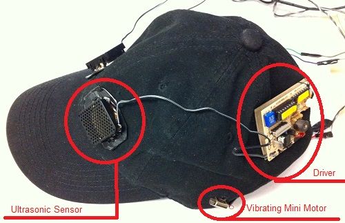
We designed and developed a device that will give more freedom in navigation to the visually impaired. Our device is composed of two sonar ranging sensors subtly placed on a baseball cap. The two sensors in conjunction with a microcontroller can provide a plethora of information regarding the surroundings near the head and up to a distance of 5 meters ahead. If used with a cane or guide dog, then one can be fully informed about all potential obstacles at any angle.
The two sensors placed at different angles provide stereo information on obstacles in front of the user. This means when approaching an object. The user would know which way to turn to avoid the object. An ATMEGA644 microcontroller serves as an intermediary between the sensors and outputs. Outputs are in the form of either headphones or two vibrators. Both of which can provide stereo information to the user. Switches allow the user to choose the two output forms, turn the device on and off, and to wake the sensor up from sleep mode.
Background Math
The two sensors use sonar. We can calculate the distance from the person to the closest obstacle through calculating the distance sound would travel in the time it took for the sensor to send and receive its sonar signal. The speed of sound is 340 m/s. The sound wave has to travel from the sensor to the object and back. This means distance = 340 * time_elapsed/2. For example, the maximum time of propagation allowed in our circuit is 32 ms, which allows for a sensing distance of 5.44 m ahead.
Logical Structure
Our project can be divided into four main parts: the user control, sensor control, sensor interpretation, and the output to the user. The user control includes the switches that allow the user to choose SensCap’s mode of operation. The sensor control determines when to tell the sensor to take a measurement. The sensor interpretation receives the output from the sensor and normalizes it to control value for the sensors. The output to the user composes of sending signals to the earphones and vibrators correctly and have them correctly interpret the signals.
Program/Hardware Tradeoffs
Whether a part of our project is controlled by program or hardware depended mostly on the capabilities of the ATMEGA644 microcontroller and on the accuracy of the design. Many parts of our hardware could have been implemented by the software as well. For example, the microcontroller outputs two built-in PWM functions out of two port pins. We could have made a software version of the PWM function, which would make it unnecessary to have a multiplexer IC chip. However, this may make the circuit inaccurate because the PWM function, especially for the headphones, require very accurate timing, that can only be achieved with hardware. This required us to output PWM for both the headphone and vibrator from the same pin and send them to their respective parts through additional hardware.
However, some parts of our project had to be hardware. For example, because of the large inductive spikes caused by motors like the vibrator, we had to optoisolate our microcontroller from the vibrator to prevent the spikes to blow out pins. Since this serves as the express purpose of protecting our program, this had to be hardware.
Standards
In Multisensor Strategies to Assist Blind People: A Clear-Path Indicator (See References), the author defined criteria for the design of devices used in the assistance of blind people. For clear-path indicators, which our device falls under, the important sensory functions must agree with the degree and redundancy suggested by medical scientists and engineers, and must be versatile to accomodate individual differences, skill, and abilities. In addition, there must be measurement of the device’s performance in simplicy of use, users’ ability in avoiding obstacles, and specific satisfaction resulting from cost, efficiency, and reliability. How well we met these standards are detailed below.
Hardware Design
Microcontroller
We used a custom targetboard designed for the ATMEGA 644 microcontroller by Bruce and Chun. We used several of the microcontroller’s functionalities. Use all three timers–0 and 2 for the pulse width modulation of the output to the user, and 1 for the input capture for interpreting the sensor results. The PWM mode outputs a digital signal that when passed through a low pass filter averages to an analog signal. This was useful to output voltages other than VDD and GND to our outputs, such as that in a sinusoid for the headphones. The MCU had a clock of 16M Hz.
SENSOR CONTROL
Sensor
Our circuit uses two SensComp 6500 each with its own SensComp 7000 Transducer for transmitting and receiving. The SensComp 6500 is controlled by an initialization (INIT) signal which is sent from the microcontroller. When a SensComp 6500 receives an INIT, it transmits 16 pulses using the transducer and receives the pulses that have bounced off of objects. This sets off our ECHO signal. The time between the INIT signal going high and the ECHO signal going high is the time it took to travel from the sensor to the nearest object within 17 degrees from straight ahead.
According to their datasheet, the sensors have a beam angle of 17 degrees. The angle between the sensors depend on the size of the wearer’s head. We aimed to have about 10 degrees of overlapping, so that if an object is directly ahead of the user, both left and right would vibrate and play sounds. Stereo is achieved in the additional 7 degrees on the left and the 7 degrees on the right.
We interspersed the INIT signals from the two SensComp 6500 to avoid cross-talk. One device is on while the other is off. Each sensor outputs a signal at 638 ms, so the left and right outputs at every 319 ms.
SENSOR INTERPRETATION
Trigger
To measure the time that it took for the sensors’ signals to travel from transducer to object and back, we used Timer1’s capture mode. We have two Senscomp 6500 devices, so they had to share the same D.6 capture pin. Since one is on while the other is off, and thus mutually exclusive, we can simply use an OR gate between the two ECHO signals. For the OR gate, we used the MM74C32N, a Quad 2-Input OR Gate IC chip. In our program, we decode this OR gate by remembering whether the left or right sensor last outputted, so the newly captured value would be associated the sensor that was used. One of these values would be associated with the left earpiece and left vibrator, while the other would be associated with the right earpiece and right vibrator.
OUTPUT TO USER
Headphones
We used a set of headphones. The headphones are set up using simple low pass RC filters. The varying voltages of the sine waves are output using pulse width modulation (PWM). We had to average over these PWM’s with low pass filters. We used a PWM time period of 15us, for a frequency of 67 kHz. Use an RC filter of 50kOhms and 10nF, for a time constant of 500us, averaging over enough of the PWM to smooth it over.
Vibration
We used vibrating mini-motors for the vibration feedback mechanism. The more voltage applied, the stronger the device vibrates. Because the vibrators are mini motors, they must be optoisolated from our microcontroller so that their large inductance spikes will not destroy our port pins. We used the 4N35 phototransistor for this purpose.
When we originally hooked up a voltage from the optoisolator to the vibrator, we found it did not run. We believe this is because the voltage was not driven strong enough by the optoisolator so the vibrator brings it down to zero. We fixed this by modeling our circuit after Lab 4, where we added in a BUZ73 to drive the motor.
Because the motor vibrates by itself, without needing the varying voltages that headphones do, we did not need to use a sineTable lookup table. We output a constant to the motors using PWM. Because the vibrator needs to use an optoisolator, we had to decrease our PWM time period to 7.5 ms, for a frequency of 133.3 Hz. The vibrator motor is a lowpass filter itself, so we did not need to add the RC filter as we did for the headphone.
We originally placed the mini motors on the inside of the hat for subtlety, but the motors were too sensitive to touch. They stopped moving with even the slightest adjustment in hat position. We then placed them on the hat, and it worked better, but with some problems documented below.
Switch Between
The headphone and vibration modes both use the same PWM ports, but are driven by different PWM modes and frequencies. We let the user switch between the two. Use MC14066BCPG, Quad Analog Switch/Quad Multiplexer IC chips so that the headphones would not be driven in vibration mode and vice versa. We output outputMode and its complement to choose whether the two PWM signals would go to the headphones or the vibrators.
We had a lot of difficulty with this simple chip. Both vibrator and headphones were on even though only one was supposed to be on. One would turn off when we start probing the IC chip to see what was wrong. We realized the problem was that the outputMode was not being driven effectively to ground by itself. We assisted it by adding in a pull-down resistor of 1M Ohm to help it settle down to zero. This let our multiplexer effectively turn off one of the outputs.
Another problem we ran into was that in vibrator mode, small spikes of voltage still seeps through to the headphones, resulting in audible clicks every time the sensor sends out pulses. Since the sensors take measurements every 319 ms, the frequency of these clicks are roughly 3 Hz. We realized we can just high pass filter it out in vibration mode without affecting the higher frequencies in headphone mode. We used a simple RC high pass filter of 0.1uF and 5.1kOhms, which removed the clicking noise effectively.
USER CONTROL
Switches
The user controls SensCap operation with three rocker switches. One of the switches turns the microcontroller on. Another switch turns the sensors on. In order to have the SensCap fully functioning, both of these switches must be turned on. Our third switch allowes the user to switch between the headphone and vibrating modes. The switches that we found in the ECE 4760 lab and bought are on-off switches which allow for switching between open and short circuits. This was a problem since we needed the switches to switch from Vdd to ground. We solved this problem by attaching a 50K Ohm pull up resistor. When the switch is in its open circuit state, the output voltage will go to Vdd. When the switch is in its short circuit state. Its resistance is much smaller than 50k Ohms. By voltage division, the output voltage drops to Gnd.
Portability
In order for this device to be easy to use and practical for the visually impaired, we had to carefully design the wearable components of this device. We chose to use a baseball cap as opposed to any other kind of hat because it is easy to instruct how the hat should be worn. The brim of the cap should be worn facing forward. This is important because the sensors are fixed to the cap and must face the correct direction in order to operate in a helpful manner. In addition, many people wear baseball caps, so the SensCap would not stand out.
Next, we chose to use a hip pack in order to allow this device to be “hands free.” The user will probably be using one hand to use a cane and it is important not to impede the user’s motion. The hip pack has switches on the side that should be facing forward. Each switch has a raised dot on it to indicate the “on” position and vibration mode. In the hip-pack, the circuitry is completely separated in its own zippered compartment from any area that the user touches. Also, there is a separate component for storing all of the batteries. This is to keep anyone using this device from touching the actual circuit.
 ar
ar
To be completely portable, we powered our device with batteries. The microcontroller was powered by a 9V battery, while the rest of the circuit was powered by 4 AA 1.5V batteries. While the microcontroller worked immediately. The rest of our circuit did not operate with the 6V provided by the 4 AA batteries. We believe this was because we were close to the maximum voltage allowed for the sensors, and thus weren’t operating correctly. We fixed this problem by adding in a diode between the VDD of the battery pack and VDD of the circuit. This effectively dropped the VDD voltage down to 5V, which let our circuit work correctly.
Parts List:
| Part Name | Part # | Vendor | Cost |
|---|---|---|---|
| Ultrasonic Sensor | SenseComp7000 | Previously Owned | $0 |
| Sensor Ranging Module | SenseComp 6500 | Previously Owned | $0 |
| Hip Pack | Previously Owned | $0 | |
| Baseball Cap | Previously Owned | $0 | |
| 9V Battery | ECE 4760 Lab | $2.00 | |
| 9V and AA Battery Holders | ECE 4760 Lab | $0 | |
| Headphones | MB770G/B | Previously Owned | $0 |
| Vibrating mini-motor | DCM-382 | All Electronics – ECE 4760 Lab | $0 |
| Complete Custom Target Board | Custom | ECE 4760 Lab | $7.00 |
| Microcontroller | Atmel MEGA644 | ECE 4760 Lab | $8.00 |
| Rocker Switches | 30-16096 | Ohm Electronics | $5.98 |
| AA Batteries | AA Batteries | Amazon | $5.34 |
| Solder Board and Components | ECE 4760 Lab | $10.00 | |
| Total | $38.32 |
For more detail: Sonar SensCap Using Atmega644