Summary of SPI (serial peripheral interface) using AVR microcontroller (ATmega16)
Serial Peripheral Interface (SPI) is a synchronous, full-duplex serial protocol used for high-speed data transfer between two devices (master and slave). AVR microcontrollers include on-chip SPI supporting both roles. SPI uses MOSI, MISO, SCK and SS lines; the master provides the clock on SCK and controls slave selection via SS. Data is shifted through SPDR with one bit per clock (8 clocks per byte). Key control is via SPCR bits (SPIE, SPE, DORD, MSTR, CPOL, CPHA, SPR1, SPR0) and SPSR SPI2X to set clock rate and operation.
Parts used in the SPI with AVR microcontroller:
- AVR microcontroller (example ATmega16)
- SCK (Serial Clock) pin
- MOSI (Master Out Slave In) pin
- MISO (Master In Slave Out) pin
- SS (Slave Select) pin
- SPDR (SPI Data Register) buffer
- SPCR (SPI Control Register)
- SPSR (SPI Status Register) including SPI2X bit
- Clock source provided by master
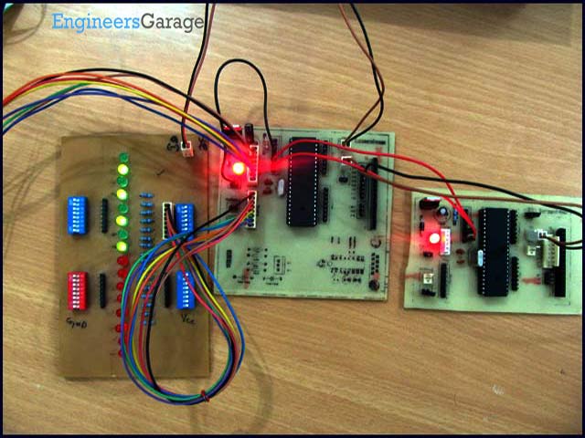
There are different protocols for serial communication between two deceives like, USART, SPI, I2C etc. Before selecting any communication protocol, data transfer rate is an important parameter. SPI transfers data at high speed data. AVR microcontroller contains on chip SPI interface. This article will explore the hardware configuration and programming of SPI.
Serial Peripheral Interface is a synchronous, full-duplex protocol. SPI is also known as “3-wire interface” protocol because it needs 3 communication lines named MISO, MOSI and SCK. SPI protocol needs two devices for communication. One of them is considered as a MASTER and another one as a SLAVE. AVR microcontrollers contain both MASTER and SLAVE interface on single chip. Thus, a microcontroller can work as both master and slave device.
SPI interface:
Besides the MISO, MOSI and SCK pins, the SS is also included in SPI system. This pin is used to select slave device. Following table explains functionality of these pins:
How SPI works:
The SPI is synchronous data transfer protocol, so clock pulse is needed to synchronize both master and slave device. The clock pulse is generated from master side. The SCK pin of master provides clock pulse to slave device.
To make any device as master, the SS pin must be set as high. If it is configured as an output pin, then it made high using the software. If the SS is considered as input pin, it should make high externally. In slave mode SS is always an input pin, which should be connected to ground (to make it slave device).
The “MOSI” stands for “master output slave input”. So, the MOSI pin works as output pin for master device and input pin for salve device. Both master and slave devices contain a buffer register, called SPDR. Master transfers one bit from its SPDR to slave device in every clock cycle. It means to send one byte data, 8 clock pulses are needed.
Registers of SPI System:
The SPI system consists three register which are described below:
1. SPCR (SPI control register):
|
SPIE
|
SPE
|
DORD
|
MSTR
|
CPOL
|
CPHA
|
SPR1
|
SPR0
|
SPIE (SPI Interrupt Enable) – To enable SPI interrupt this is set as high.
SPE (SPI Enable) – SPI system is enabled when this bit is set.
DORD (Data Order) – For DORD=1, LSB will be transmitted first.
For DORD=0, MSB will be transmitted first.
MSTR (Master/Slave Select) – For MSTR=1, to select device as master.
For MSTR=0, to select device as slave.
SPR [1:0] (SPI clock Rate) – This SPR [1:0] and SPI2X bit of SPSR register decides frequency of SCK. The combination of these three bits to select SCK frequency are shown in following table:
- What is SPI?
SPI is a synchronous, full-duplex serial communication protocol for high-speed data transfer between master and slave devices. - Which pins are used in SPI?
MOSI, MISO, SCK and SS pins are used in SPI. - How many clock pulses are needed to send one byte via SPI?
Eight clock pulses are needed to send one byte since one bit is transferred per clock cycle. - How is a device made master in SPI on AVR?
Set the MSTR bit in SPCR to 1 to select the device as master and ensure SS is configured high if SS is an output. - How is a device made slave in SPI on AVR?
Set MSTR bit in SPCR to 0 to select slave mode and ensure SS is held low as an input to keep it in slave mode. - What does DORD bit control?
DORD selects data order: DORD=1 sends LSB first, DORD=0 sends MSB first. - Which register enables SPI interrupt?
Set the SPIE bit in the SPCR register to enable SPI interrupt. - How is SPI enabled or disabled?
Set or clear the SPE bit in the SPCR register to enable or disable the SPI system. - How is SPI clock frequency selected?
The clock frequency is selected using SPR1 and SPR0 bits in SPCR together with the SPI2X bit in SPSR.