Summary of STEREO 64LEDS VU METER CIRCUIT ATMEGA8
This article details a cost-effective 2x32 LED VU meter project using an ATmega8 microcontroller. By rapidly switching four LED columns, the design controls 64 LEDs with limited I/O pins, offering superior value compared to standard LM3915 chips. The circuit includes a 7805 voltage stabilizer, audio input adapters with sensitivity trimmers, and transistors for column switching. The author provides assembly instructions, PCB layout tips, and source code for programming the microcontroller to visualize audio levels.
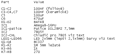
Parts used in the 2x32 LED VU Meter:
- ATmega8 microcontroller
- 7805 5V voltage stabilizer
- R1 and R2 trimmers
- Switching transistors
- 64 LEDs (2 rows of 32)
- 2 power-on indicator LEDs
- DIL28PZ 7.5mm socket
- Heatsink (cooler) for the stabilizer
- Screw terminals or direct wire connections
Lately, when I went deeper into programming, I was fascinated by precise A / D converters in microcontrollers. And so I decided to make a 2×32 LED VU meter with the ATmega8 microcontroller, which can be bought for example in GME for only 34Kc, and so it comes out much cheaper than the LM3915 which also serves as a VU meter, but only for 1×10 LEDs.Perhaps it is strange how I can control the 64 LEDs with I / O pins. This is solved by simply switching 4 columns with LEDs at high speed.
Photo of a VU meter constructed in a non-soldering field:
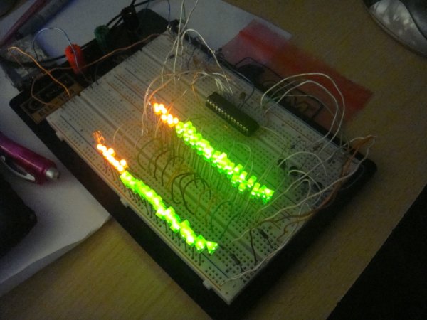
Photo of finished VU-meter:
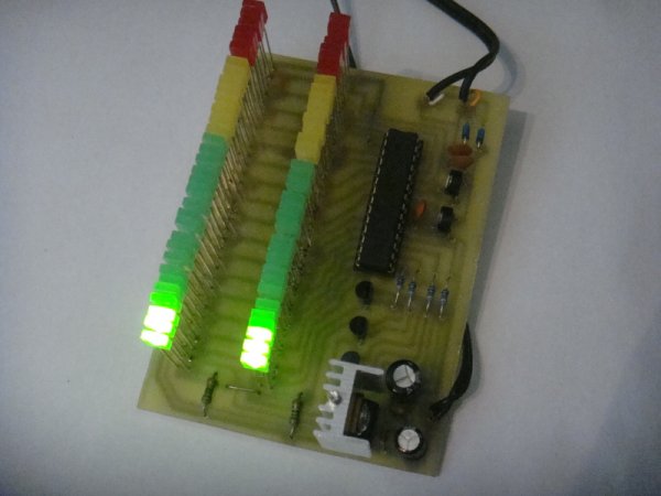
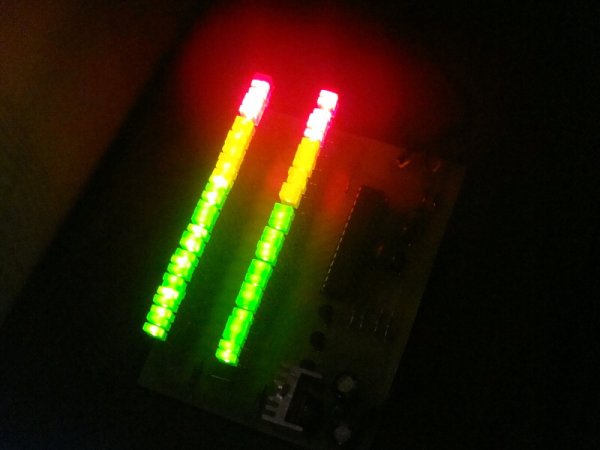
Photo of the finished VU-meter by dark:
Diagram
The circuit diagram is very simple. In the top right is a 5V stabilizer. If you have a directly stabilized 5V 400mA available, you can drop this part, but most of this will be used in amplifiers where we do not have stabilized 5V. The cooler must be placed on the 7805 stabilizer. The size of the chiller is given by the supply voltage, if the power supply is 12V, it will lose up to 3W, and there is still a relatively small cooler (see photo). However, at higher feed voltages, it is better to roll the stabilizer onto the wires and place it on a large cooler.
Below the Schematic Stabilizer, input audio adapters for A / D converters in the microcontroller. Set R1 and R2 trimmers to set the required sensitivity to the input signal.
On the right-hand side are transistors that quickly switch individual LED columns. And on the left are the LEDs themselves. LEDs need not be connected via any resistor due to the internal resistance of the microcontroller which limits the current to the LED to about 80mA, and due to the rapid switching of the 4 LED columns, a PWM modulation will be created to ensure that a current of about 20mA flows into one LED. Below 2x32LED LEDs there are 2 LEDs that are lit continuously and serve as power-on indicators.
In the center is the C3 microcontroller itself, which minimizes the A / D converter noise.
Diagram:

List of parts:
DPS
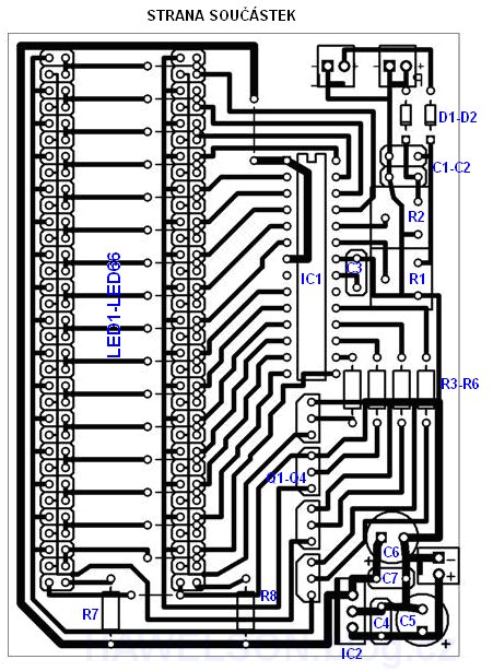
When making PCBs, we pay attention to LED fields, where copper strips are close to each other, whether bad etching is not where they are to be connected.
When installing, be sure to first install 2 wire jumpers out of the leds and 16 LED jumpers. For PCs, I have long hesitated for what LEDs to create it. Originally I wanted to do it for 5mm LEDs, but the PCB would have to be very long (at 5mm spacing of 33cm in length), so I finally decided to make the PCB for 2x5mm LED, respectively 2.5x5mm. These LEDs are quite cheap to get, and in addition to the LEDs, it can be adjusted to any large LED.
We place the socket (DIL28PZ 7.5mm) on the IC1 slot so that we can easily program the microcontroller and eventually insert it into the PCB. We will not forget to place the cooler on the IC2.
At the place of the voltage and signal supply, we can either put the screw terminals into dps or simply lead the wires directly into the PCB.
PCB component side:
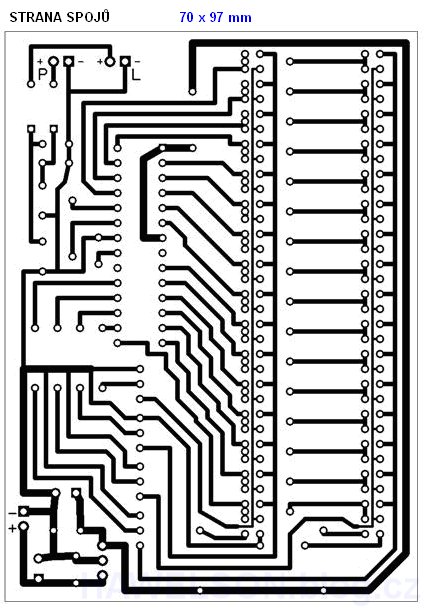
DPS link page:
Programming
For a complete description of the programming, refer to the Programming ATMEL microcontrollers .
So just copy the text below, copy it to the Notepad and save it with the .hex extension (eg VUmetr.hex). Then upload this hex file using PonyProg to the microcontroller.
The source code in C is uploaded HERE , you need to copy the code to the Notepad and save it with the .c or paste it directly into the development environment (avr studio).
The LED flashes at about 100Hz for as little noise as possible but can programmatically increase this frequency to 20kHz, but when you disconnect from the sound source, you hear a gentle whistling in the amplified sound.
Source: j.mp/aPvvO6 VU Meter Circuit files alternative link: atmega8-vu-metre-iki-kanal-64-led.rar
- How does the project control 64 LEDs with limited pins?
The system switches 4 columns of LEDs at high speed to create PWM modulation. - What is the purpose of the 7805 stabilizer in this circuit?
It provides a stabilized 5V power supply for the microcontroller and other components. - Can resistors be used for the LEDs in this design?
No, internal resistance limits the current, so external resistors are not required. - How can the switching frequency be adjusted in the code?
The frequency can be increased from 100Hz to 20kHz programmatically. - Why did the author choose 2.5x5mm LEDs over 5mm ones?
Using smaller LEDs prevents the PCB from becoming excessively long (33cm). - What happens if the switching frequency is set too low?
A whistling sound may be heard in the amplified audio when disconnected from the sound source. - Which software tool is recommended for uploading the hex file?
PonyProg is used to upload the .hex file to the microcontroller. - Where should the heatsink be placed on the board?
The cooler must be placed on the IC2 slot where the 7805 stabilizer is located.