Summary of TRANSISTOR TESTER CIRCUIT ATMEGA8 LCD DISPLAY
This article describes a transistor tester circuit built around the ATmega8 microcontroller, featuring an LCD display for identifying various electronic components like BJTs, MOSFETs, and thyristors. The device automatically recognizes component types, calculates pin configurations, and measures electrical properties such as gain and threshold voltage within two seconds. Powered by a 9V battery with a 78L05 regulator, it operates via a single button and includes an automatic shutdown feature to conserve power.
Parts used in the Transistor Tester Circuit:
- ATmega8 microcontroller
- 9V battery
- 78L05 voltage regulator
- 470 k resistor
- 680Ω resistor
- HD44780 compatible 2×16 character text LCD
- Three transistors for automatic shutdown circuitry
- Test inputs (no protective circuit)
Transistor very useful for testing the circuit, but I do not know more pic programming with atmel series in seeing this type of advanced applications get confused 🙂 Transistor test circuit, BJT, MOSFET, triac,…Electronics Projects, Transistor Tester Circuit ATMega8 LCD Display “atmega8 projects, avr project, microcontroller projects, “
Transistor very useful for testing the circuit, but I do not know more pic programming with atmel series in seeing this type of advanced applications get confused 🙂
Transistor test circuit, BJT, MOSFET, triac, thyristor, JFET transistors and diodes can be measured. Source software and diagrams drawn with eagle pcb files there.
ATMEGA8 TRANSISTOR TESTER
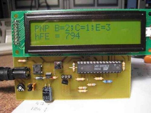
When the microcontroller ATmega8 has been selected. He has more than enough flash and RAM. He also has enough port pins and is very reasonably priced. The transistor tester is powered by a 9V battery. The 5V operating voltage for the AVR is quite conventionally generated with a 78L05. On port B of the ATMega8 various resistors are connected: the transistor pin a large (470 k) and a small (680Ω). Hereby two different currents can be applied to the test pin. The resistors are connected to ADC0, ADC1 and ADC2. At these pins and the transistor under test is connected. The left part of the circuit (with the 3 transistors) is responsible for the automatic shutdown. More on that later. On the first pins of port D, the LCD is connected. This is a 2×16 character text LCD with HD44780 compatible controller.
It should be noted that the test inputs do not have a protective circuit. A suppressor would probably distort the measurement results. It should therefore not be components that are still installed in a circuit under test. Otherwise, the ATMega8 could be damaged.
TRANSISTOR TESTER CIRCUIT FEATURES
Automatic recognition of the NPN and PNP transistors, N-and P-channel MOSFETs, diodes (including double-diode), thyristors, triacs and resistors and capacitors.
Automatic calculation and display of the pins of the component to be tested
Detection and display of the protective diodes for transistors and MOSFETs
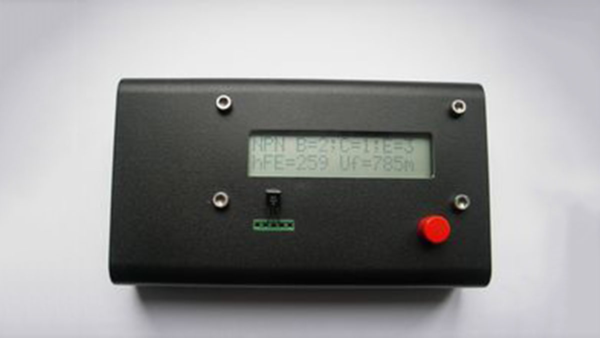
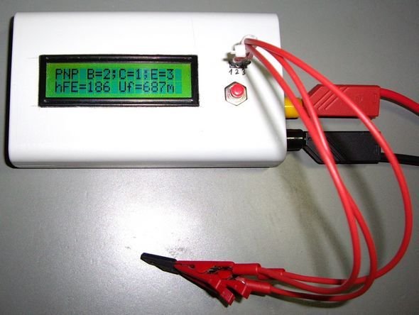
Determining the gain and the base-emitter forward voltage at transistors
Measurement of the gate threshold voltage and gate capacitance of the MOSFET
Display the values on a text LCD (2 * 16 characters)
Duration of a component testing: Less than 2 seconds (Exception: larger capacitors)
One-button operation; automatic shutdown
Power consumption in off mode: <20 nA Source: http://www.mikrocontroller.net/ Transistor Tester Circuit files alternative link: transistor-tester-circuit-atmega8-lcd-display.rar alternative link2 alternative link3
- What components can this tester identify?
It identifies NPN and PNP transistors, N- and P-channel MOSFETs, diodes, double-diodes, thyristors, triacs, resistors, and capacitors. - How is the 5V operating voltage generated?
The 5V is conventionally generated using a 78L05 voltage regulator from the 9V battery supply. - Can I test components while they are still installed in a circuit?
No, the test inputs lack a protective circuit, so testing installed components could damage the ATMega8 or distort results. - What is the duration of a component test?
The testing duration is less than 2 seconds, except when measuring larger capacitors. - Does the device have an automatic shutdown feature?
Yes, it features one-button operation and an automatic shutdown mechanism controlled by three specific transistors. - How much power does the device consume in off mode?
The power consumption in off mode is less than 20 nA. - Which pins on the ATMega8 are used for the LCD connection?
The LCD is connected to the first pins of port D. - What parameters are calculated and displayed for transistors?
The device displays the base-emitter forward voltage and determines the gain of the transistors. - How are different currents applied to the test pin?
Two different currents are applied using a large 470 k resistor and a small 680Ω resistor connected to port B.