Introduction
This project implements a microcontroller based temperature regulator which can be controlled via the Ethernet port on any common personal computer.
As the world becomes more networked, the power of our ability to communicate with many different systems instantly continues to prove it’s worth in maximizing utility and convenience. The common consumer now has more options then ever for networking access from hand held Blackberries to common Internet access through a personal computer. Many systems would only benefit from being accessible from any network connection, including many common devices that previously would never be considered to be networked, such as a coffee machine or refrigerator.
In our case, we pair a microcontroller with a commercial Ethernet solution via SPI in order to allow the world at large to communicate with the microcontroller, and vise versa. Communication in our device is done through a modified UDP controller accessed via the command prompt and third party software. As a proof of concept, we used the ethernet controller to sample and set temperatures for a closed system. Temperature sensing is done through the analog to digital converter on the microcontroller and heating and cooling is done using the pulse width modulator in conjunction with proportional control theory to allow for a stable transition to the desired temperature.
High Level Design
Rationale
Although the benefits of Ethernet-capable microcontrollers are numerous, we focused on remote sensing and control benefits allowed by the technology. In theory similar systems could be used to cool or heat different parts of a house, office, car, lab or other area that needs remote temperature control from anywhere in the world. This specific implementation was chosen as a possible value-add to a product created by a Cornell graduate student. His product, KoolKennel ostensibly uses a similar methodology of heating or cooling pet carriers. By adding Ethernet capability, pet owners can both check and adjust the temperature of the kennel remotely. The general concept of remote temperature measurement and control has other lucrative applications in a variety of other industries as well.
Logical Structure
The design was divided into two equally important parts. First, we needed the microcontroller to measure and regulate the temperature in our system. We used a thermistor with the analog to digital convector on the microcontroller, and a peltier device attached to a fan to cool or heat our system. Due to the size of our system compared to our peltier device we needed to not only change our temperature quickly but to stabilize at a point. Thus we chose to implement a version of a proportional controller. The peltier device is controlled by a H bridge implementation to increase the voltage driving the device.
The Ethernet connection to the device provides our only means of communicating with the system and thus was the other significant part of the project. The first step in establishing Internet connectivity was to find a means of interfacing our microcontroller with Ethernet connectivity. Research on similar projects showed that available options included chips from Realtek, SMC, and Microchip. After finding no full implementations for the Microchip controller written on the Codevision compiler, we decided to take the problem on and implement it ourselves.
Hardware/Software Trade offs
Since the analog to digital converter on the microcontroller could only sample one reading at a time we limited ourselves to using only one temperature sensor in the device. While a larger space might require a sensor network to accurately measure the entire system. Our environment was small enough that we could use only sensor to satisfactory results. Additionally, since we used a motor to increase air flow into and out of the system we introduced an irremovable amount of thermal noise into our system that would vary the temperature constantly and thus would keep changing the input to the ADC on the microcontroller.
This meant that we would need to introduce a software filter for the temperature reading. Additionally our PD control was limited by this thermal noise, and we can only be as accurate as our reading. Due to our limited budget we chose to make our own boards, but this increased the amount of inductance in the system. Thus implementing the three way handshaking protocol was much more difficult then we first perceived as the analog hardware introduced noise that would invalidate packets. UDP protocol provided a simple enough system that would not be affected by the electromagnetic reflections that might result from the system, and thus determined our choice of protocol. Our choice in using UDP necessitated additional code to interact with the device through Windows. Fortunately, free third party software referenced in the appendix was already written to achieve this.
Standards
We followed a wide variety of standards for Ethernet, Address Resolution Protocl (ARP), Internet Protocol (IP), ICMP (Internet Control Message Protocol) TCP (Transmission Control Protocol) DHCP (Dynamic Host Configuration Protocol).
Ethernet needed to be built so that packets could go in and out; ARP was to be built on top of Ethernet to allow for other computers to discover the existence of our controller; IP needed to be built in order to provide transport of our packets; ICMP was to be built so that we could effectively ping our controller; TCP was to be used as the main transmitter of packets; DHCP was to be enabled so that a router could dynamically assign an IP address to our controller. This report is not intended to be a discussion of these protocols and their complete function as that is a class in and of itself, but we followed all protocols as specified here.
Patents and Legal Considerations
While our design intended to enhance existing temperature controlled systems, our novel way of achieving this does not infringe on any patents that we could find.
Program/Hardware Design
Overall Design
Our choice to use the Microchip ENC28J60 determined many of the hardware choices that we made in our design process. As the device runs off of 3.3 volts instead of logical 5 volts. We originally envisioned stepping up the voltage using a pack of AND gates. Since the Ethernet controller needed to be run at a high frequency we were not able to spec AND gates fast enough that would both fit into our budget and have slew rates fast enough. Thus we chose to run our microcontroller at 3.3 volts as well.
Resistors and connections between the ENC28J60 were determined by the ENC28J60 data sheet. As well as the connections between the Ethernet jack and the Ethernet controller. The Ethernet jack features not only transmission and receive lines but functional LEDs as well, who also operated on the 3.3 volts. Since we needed both a 3.3 volt line and a 12 volt line for our H-bridge we used a converted ATX power supply that we already owned.
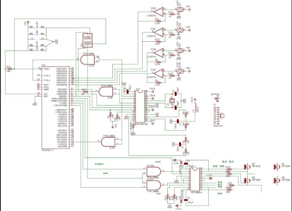
The following schematic shows our overall design of the microcontroller, with all the ports appropriately attached.
Temperature Measurement and Control
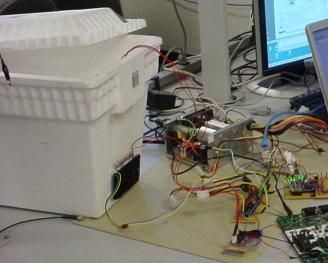
Measurement of our system was performed by measuring the voltage across a variable thermistor, specced to have 10mV / degree F. The ADC on the microcontroller however needs to be more precise then that, however, and so we fed this same voltage across a simple op amp specced to have a gain of three. With the microcontroller operating at 3.3 volts this allowed us to detect temperatures up to 110 degrees F. Our temperature contained system consists of a large styrofoam box whose only interface with the outside enviroment is our peltier element attached to a fan to increase circulation.
This fan, however, generated enough heat that we could not sufficiently cool the system as we had hoped we would be able to. We were still able to sufficiently heat the system above room temperature and keep it there, but due to thermal leakage into our system and the heat generated by the fan we were not able to cool the system below 70 degrees. At first we were not achieving the thermal rate of change that we expected, but including another external fan on the device allowed us to cool the peltier, a differential device, and achieve larger thermal changes including additional cooling.
The thermal energy that the fan adds into the system is also seen in measuring the thermistor. The thermistor, pickup up this slight variation, amplifies this variation for the ADC. Since our controller has a limited reaction time to cooling and healing, we needed to slow the measurement of our system as well and decided to implement a running average filter and impose an artificial time between temperature measurements. The running average filter measures the last eight inputs and we use this averaged output to determine the temperature. This allowed us to fine tune our thermal controller to a satisfactory level and reduced the amount of variation that the fan introduces. Before integrating the thermal part of our system we relied heavily on LEDs controlled by the MCU, but due to cost we did not include them in our final design as they only served in debugging purposes.
Parts List:
| Part | Supplier | Cost |
|---|---|---|
| Peltier | Bgmicro | $8.00 |
| Mega32 | LAND | $8.00 |
| Boards | LAND | $2.00 |
| ENC28J60 | Microchip | SAMPLE |
| 74HCT08 | Digikey | $0.50 |
| L829-1J1T-43 | Digikey | $6.40 |
| 25 MHz Crystal | Digikey | $0.70 |
| HIP4081A | Digikey | $3.00 |
| IC Sockets | OWNED | |
| IRF520 | OWNED | |
| LM324N | Digikey | $0.45 |
| Styrofoam Box | OWNED | |
| LM34 | National | SAMPLE |
| Power Supply | OWNED | |
| Heat Sinks | OWNED | |
| TOTAL | $29.05 |
For more detail: UDP/Ethernet Controlled Temperature Regulator Using Atmel Mega32