Summary of Upgrade DIY Mini DSO to a Real Oscilloscope With Awesome Features
This article describes an upgraded DIY Mini DSO oscilloscope: hardware, new features (frequency display, adjustable trigger, multiple trigger modes, waveform scrolling, brightness), specifications, circuit change (LED indicator), parts, software download and programming, user interface, controls via an EC11 encoder, operation modes, and usage tips including pre-sampling behavior and saving settings to EEPROM.
Parts used in the Mini DSO:
- MCU: STC8A8K64S4A12 @27MHz
- Display: 0.96" OLED 128x64
- Controller: EC11 Encoder
- Input: Single channel input circuitry (voltage divider)
- LED x 1 (indicator)
- Resistor 5k x 1 (for LED)
- Voltage divider resistors (example: 10k and 2k mentioned)
- High temperature tape (for protection)
- USB to TTL downloader
- Miscellaneous wiring, PCB or breadboard components
Last time I shared how to make a Mini DSO with MCU.
To know how to built it step by step, please refer to my previous instructable:
https://www.instructables.com/id/Make-Your-Own-Osc…
Since many people are interested in this project, I spent some time upgrading it overall. After upgrading, the Mini DSO is more powerful.
Specification:
- MCU: STC8A8K64S4A12 @27MHz Get it from AliExpress
- Display: 0.96″ OLED with 128×64 resolution Get it from AliExpress
- Controller: One EC11 Encoder Get it from AliExpress
- Input: Single Channel
- Sec/div: 500ms, 200ms, 100ms, 50ms, 20ms, 10ms, 5ms, 2ms, 1ms, 500us, 200us, 100us100us only available in Auto Trigger Mode
- Voltage Range: 0-30V
- Sampling Rating: 250kHz @100us/div
New features:
- Show frequency of waveform
- Customize trigger level
- Auto, Normal and Single Trigger Mode
- Scroll waveform along horizontal or vertical
- Adjust OLED brightness in settings
Step 1: Watch the Video!
In this video, I will show you the changes, operations and functions about the new version Mini DSO.
Step 2: Prepare Your Part!
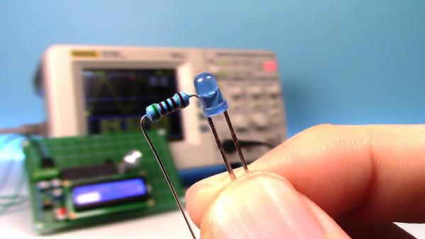
We need to add an indicator for new functions.
Material List:
- LED x 1 Get it from AliExpress
- Resistor 5k x 1 Get it from AliExpress
Step 3: Scheme and Circuit!
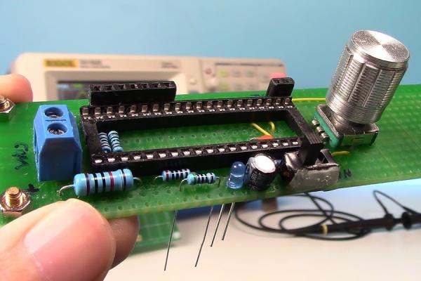
The changes in circuit is only to add a LED as indicator.
I will show you the use of the indicator later.
Protection of the circuit:
Last time I made a case with foam. The foam may produce static electricity. This issue need to be paid attention definitely.
This time, I use high temperature tape to do the protection.
Step 4: Download the Code!
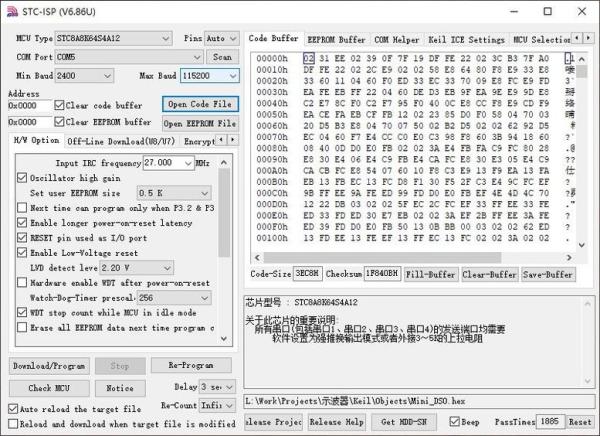
Download the package below. There are source code and compiled hex file.
Also, available on GitHub: https://github.com/CreativeLau/Mini-DSO
If you do not want to read the codes, just burn the hex into the MCU.
Use a USB to TTL downloader and STC-ISP software to download the code to MCU.
Connect TXD, RXD and GND.
Download STC-ISP software here: http://www.stcmicro.com/rjxz.html
If the interface of STC-ISP is Chinese, you could click upper left icon to change the language to English.
For the detail configuration of STC-ISP please refer my previous video.
The codes were written in C. Use Keil software to edit and compile it.
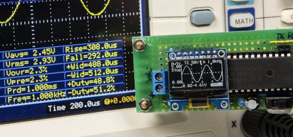
Step 5: Introduction of Interface!
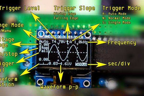
Parameters in Main Interface:
Seconds Per Division:
“500ms”, “200ms”, “100ms”, “50ms”, “20ms”, “10ms”,”5ms”, “2ms”, “1ms”, “500us”, “200us”, “100us”
100us only available in Auto Trigger Mode
Voltage Range:
Voltage is 0-30V.
Trigger Level:
Trigger voltage level.
Trigger Slope:
Trigger on Rising or Falling Edge.
Trigger Mode:
Auto Mode, Normal Mode, Single Mode.
Status in Main Interface:
‘Run’: Sampling Running.
‘Stop’: Sampling Stopped.
‘Fail’: The Trigger Level beyond the waveform in Auto Trigger Mode.
‘Auto’: Auto Voltage Range.
Parameters in Settings Interface:
PMode(Plot Mode): Show waveform in Vector or Dots.
LSB: Sampling Coefficient. Calibrate the sampling voltage by adjusting LSB.
100 times of voltage dividing coefficient. e.g. the resistor for voltage dividing is 10k and 2k, calculate the voltage dividing coefficient (10+2)/2=6. Get the LSB = 6 x 100 = 600.
BRT(Brightness): Adjust OLED Brightness.
Step 6: Introduction of Operations!
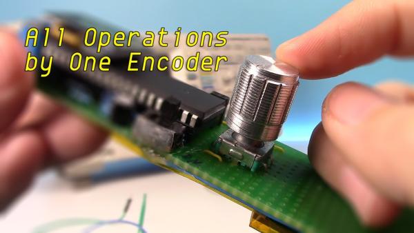
All operations are completed by the EC11 Encoder. The input include single click, double click, long press, rotate and rotate while pressing. It seems a little complicated, don’t worry, there are details below. The resources of this encoder have been almost exhausted. If there are new features, may need additional input component.
Main Interface – Parameter Mode:
- Single Click Encoder: Run/Stop sampling
- Double Click Encoder: Enter Wave Scroll Mode
- Long Press Encoder: Enter Settings Interface
- Rotate Encoder: Adjust parameters
- Rotate Encoder While Pressing: Switch between options
- Switch Auto and Manual Range: Rotate Encoder clockwise continuous to enter auto range. Rotate Encoder anticlockwise to enter manual range.
Main Interface – Wave Scroll Mode:
- Single Click Encoder: Run/Stop sampling
- Double Click Encoder: Enter Parameter Mode
- Long Press Encoder: Enter Settings Interface
- Rotate Encoder: Scroll waveform horizontally (only available when sampling stopped)
- Rotate Encoder While Pressing: Scroll waveform vertically (only available when sampling stopped)
Settings Interface:
- Single Click Encoder: N/A
- Double Click Encoder: N/A
- Long Press Encoder: Return to Main Interface
- Rotate Encoder: Adjust parameters
- Rotate Encoder While Pressing: Switch between options
Step 7: Introduction of Functions!
Trigger Level:
For repeating signal, trigger level could make it stable on display. For single-shot signal, trigger level could capture it.
Trigger Slope:
It determines whether the trigger point is on the rising or the falling edge of a signal.
Trigger Mode:
- Auto Mode: Sweep continuous. Single click the encoder to stop or run sampling. If triggered, the waveform will be shown on the display and the trigger position will be put at the center of chart. Otherwise, the waveform will scroll irregular, and ‘Fail’ will be shown on the display.
- Normal Mode: When complete pre-sampling, you can input signal. If triggered, waveform shown on the display and waiting for new trigger. If no new trigger, the waveform will be kept.
- Single Mode: When complete pre-sampling, you can input signal. If triggered, waveform shown on display and stop sampling. User need to single click Encoder to start next sampling.
For Normal Mode and Single Mode, be sure the trigger level has been adjusted correctly, otherwise no waveform will be shown on the display.
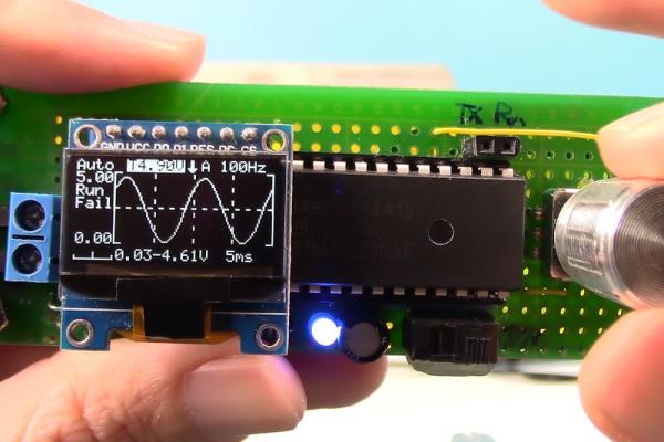
Indicator:
Generally, the indicator on means the sampling is running. The more important use is in Single and Normal Trigger Mode, before get into the trigger stage, pre-sampling is required. The indicator will not on during pre-sampling stage. We should not input signal until the indicator comes on. The longer time scale selected, the longer waiting time of pre-sampling.
Save Settings:
When exit settings interface, all parameters in settings and main interface will be saved in EEPROM.
Source: Upgrade DIY Mini DSO to a Real Oscilloscope With Awesome Features
- How do I download the code to the MCU?
Use a USB to TTL downloader with STC-ISP software, connect TXD, RXD and GND, and burn the provided hex or compile with Keil. - Can I get the source code for the project?
Yes, the source code and compiled hex are available in the provided download package and on GitHub at https://github.com/CreativeLau/Mini-DSO. - What parts are needed for the upgraded Mini DSO?
The article lists the MCU STC8A8K64S4A12, 0.96 OLED 128x64, EC11 encoder, single-channel input circuitry, LED indicator and a 5k resistor, among other miscellaneous parts. - How is the indicator used?
The indicator is generally on when sampling is running and stays off during pre-sampling for Normal and Single Trigger Modes to show when to input the signal. - Does the Mini DSO support different trigger modes?
Yes, it supports Auto, Normal and Single trigger modes. - What time divisions are available?
Seconds per division options include 500ms, 200ms, 100ms, 50ms, 20ms, 10ms, 5ms, 2ms, 1ms, 500us, 200us, and 100us (100us only in Auto Trigger Mode). - How do I adjust OLED brightness?
Brightness is adjustable in the Settings interface using the EC11 encoder's rotate function. - How do I switch between Auto and Manual voltage range?
Rotate the encoder continuously clockwise to enter auto range and rotate anticlockwise to enter manual range. - Can waveform be scrolled and how?
Yes; in Wave Scroll Mode, rotate the encoder to scroll horizontally when sampling is stopped, and rotate while pressing to scroll vertically when sampling is stopped. - Are settings preserved after exit?
Yes, settings and main interface parameters are saved to EEPROM when exiting the settings interface.