
Summary of USB TO LPT CONVERTER CIRCUIT WITH ATMEL ATMEGA8
Converter from USB to LPT parallel port (25-pin SubD) using an Atmel ATmega8 microcontroller that virtualizes parallel-port I/O instructions in hardware. It supports SPP, EPP, ECP modes, a 16-byte FIFO, USB Low Speed, suspend mode, and provides open-source schematics, PCB layouts, firmware source, and Windows drivers for legacy OSes including Windows 98–Vista.
Parts used in the USB to LPT Converter Circuit:
- Atmel ATmega8 microcontroller
- 25-pin SubD female connector (LPT parallel port)
- USB connector (type for Low Speed USB)
- 16-byte FIFO buffer (implemented in firmware/hardware buffering)
- Passive components (resistors, capacitors)
- Crystal or resonator for ATmega8 clock (if used)
- Voltage regulator or power supply components
- PCB (custom designed Eagle files provided)
- Programming header for ATmega8 firmware
- Miscellaneous connectors and mounting hardware
Converter from USB to LPT parallel port (25 pin SubD receptacle) with hardware virtualization at input/output instruction level Supports all parallel port modes named SPP, EPP and ECP, 16 Byte FIFO depth USB Low… Electronics Projects, USB to LPT Converter Circuit with Atmel ATMEGA8 “atmega8 projects, avr project, microcontroller projects, “
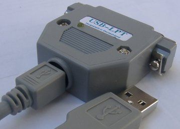
Converter from USB to LPT parallel port (25 pin SubD receptacle) with hardware virtualization at input/output instruction level Supports all parallel port modes named SPP, EPP and ECP, 16 Byte FIFO depth USB Low Speed (1.5 Mbit/s signaling; 1 kByte/s for input/output instructions) Supports USB suspend mode with reduced power consumption Full open-source, even for schematics and PCBs
In particular laptop works well with a circuit 🙂 USB port Lpt port çevriy Windows 98-Me-2k-XP-Vista driver files there is also the source. C. H. Hex code and eagle crafted with PCBs schema files are
USB TO LPT
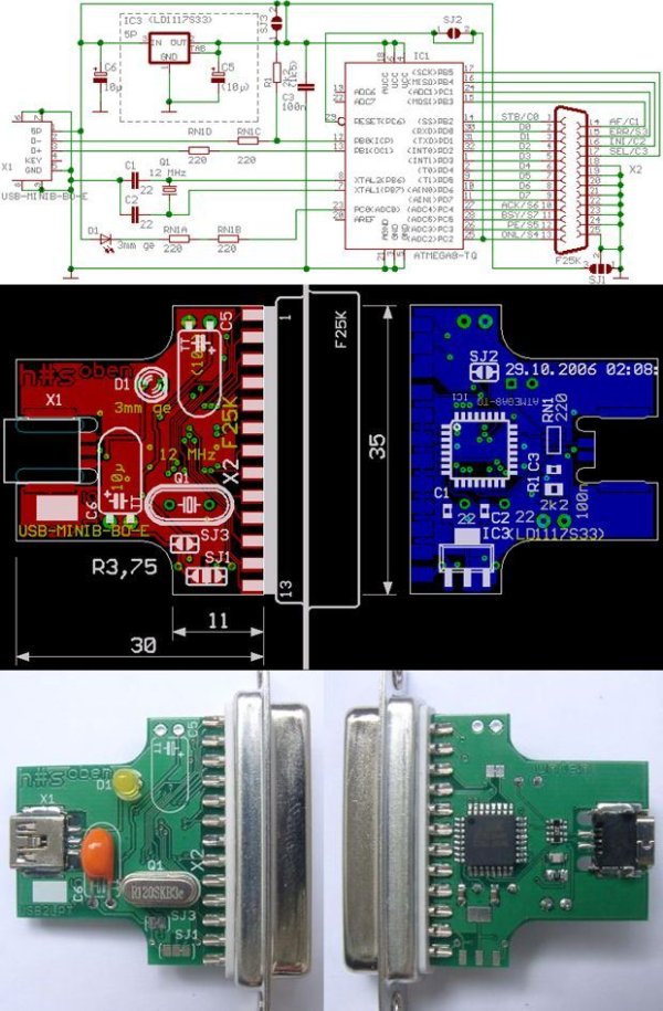
Source: USB TO LPT CONVERTER CIRCUIT USB to LPT Converter Circuit with Atmel ATMEGA8 alternative link: usb-to-lpt-converter-circuit-with-atmel-atmega8.rar alternative link2, link3
- What microcontroller is used in the USB to LPT converter?
The project uses an Atmel ATmega8 microcontroller. - Does the converter support ECP, EPP, and SPP modes?
Yes, it supports SPP, EPP, and ECP parallel port modes. - What type of USB signaling does it use?
It uses USB Low Speed (1.5 Mbit/s signaling). - Is there a FIFO for buffering data?
Yes, the design includes a 16 byte FIFO depth for buffering. - Are the schematics and PCB files available?
Yes, the project is fully open-source and includes schematics and PCB files. - Does the converter support USB suspend mode?
Yes, it supports USB suspend mode with reduced power consumption. - Are drivers provided for Windows?
Yes, Windows drivers and source are provided for Windows 98, Me, 2000, XP, and Vista. - Is firmware source code available?
Yes, the firmware source and hex code are included in the project files.
