Summary of Variable Power Supply with LCD
This project describes building an adjustable power supply using the LM317 voltage regulator and an ATMega16 microcontroller for digital voltage display. The LM317 circuit regulates the output voltage, while the microcontroller, through its ADC, measures the voltage output. A voltage divider is used to scale down the voltage from 30V to a safe 5V input level for the microcontroller. The output voltage is shown on a 16x2 LCD screen, making it an accurate and user-friendly power supply unit for electronic hobbyists.
Parts used in the LM317 Based Adjustable Power Supply with Digital Display:
- LM317 IC
- 240 Ohms Resistor
- Capacitors – 0.1uF and 10uF
- 5k Potentiometer
- 30V/1A Adapter (or Transformer + Bridge Rectifier IC)
- ATMega16 Development Board
- 16 x 2 LCD Display
- Resistors for Voltage Divider (R1 and R2)
Are you an electronic hobbyist? Then an adjustable power supply is a must for your various needs. This project explains how to make a LM317 based adjustable power supply unit with a digital display.
Components Required
1. LM317 IC
2. Resistor – 240 Ohms
3. Capacitors – 0.1uF, 10uF
4. Potentiometer – 5k
5. 30V/1A Adapter (or a transformer + Bridge wave rectifier IC)
6. ATMega16 Developments Board
7. 16 x 2 LCD Board
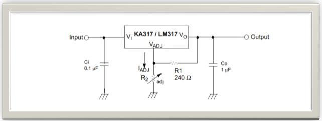
Circuit Design
Well the power supply circuit is very simple and can be found in the datasheet of LM317 itself.
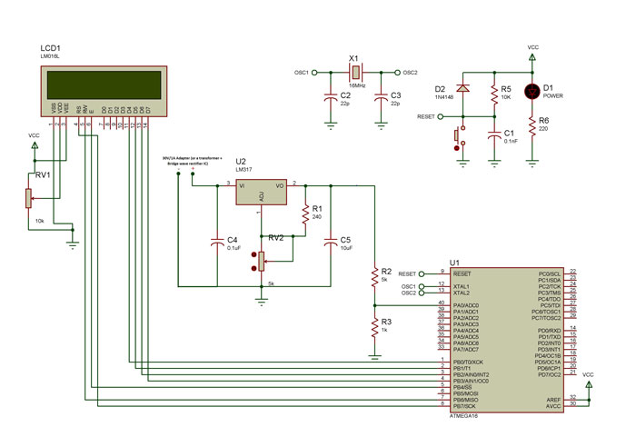
What we need to design is the additional voltmeter kind of arrangements using a microcontroller in order to display the output voltage value accurately. For this, we use the ADC feature of the microcontroller.
But the problem is that ATmega16 can only take up to 5V. Input voltage more than that can fry up the controller.
Solution: A Voltage divider circuit!
Here R1 and R2 are the resistors and Vin is the input voltage. The output voltage Vout is given as:
Vout = Vin X R2/(R1 + R2) . . . . . . . . . . . . . . . (1)
We choose the resistor values based on our requirements. Like say now our maximum voltage to be measured is 30V but we can only give up to 5V to our controller.
For more detail: Variable Power Supply with LCD