As I write this instructable it is mid winter on the Northern hemisphere and that means short days and long nights. I am used to getting up at 06:00 and in the Summer the sun will be shining by then. In the Winter though, it gets light at 09:00 if we are lucky to have a day that it isn’t cloudy (which is…not often).
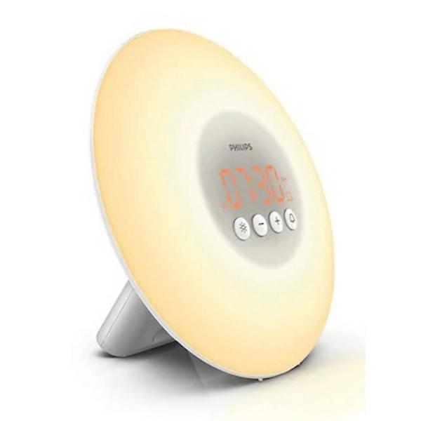
Some time ago I read about a “wakeup light” made by Philips that was used in Norway to simulate a sunny morning. I never bought one, but I kept thinking about making one because making one yourself is more fun than just buying it.
Supplies:
Picture frame “Ribba” 50 x 40 cm from IKEA
perforated hardboard from hardware store
STM8S103 development board via Ebay or others
DS1307 Real Time Clock (Mouser, Farnell, Conrad, etc)
32768 Hz watch crystal (Mouser, Farnell, Conrad, etc)
3V lithium coincell + coincell holder
BUZ11 or IRLZ34N N-channel MOSFETs (3x)
BC549 (or any other NPN transistor)
as many white, red, blue, green, etc leds as you want
some resistors and capacitors (see schematic)
Powerbrick, 12V to 20V, 3A or more (e.g. old laptop powersupply)
Step 1: Making It (a Little) Easier to Get Up
The idea is that it is hard to get out of bed in the morning when it is still dark. And if you live close or even above the arctic circle it will be dark very long. In places as Tromsö in Norway it will not get light at all as over there the sun sets half November only to re-appear halfway Januari.
So what Philips did was simulate the rising of the sun.
Philips slowly increases the brightness of a the lamp, which is probably made with several leds but hidden behind a single diffuser. Their time from off to full brightness takes 30 minutes.
The Philips wakeup lights aren’t that expensive but it has just a single colour and it looks a bit small. I think I can do better.
Step 2: More Colour
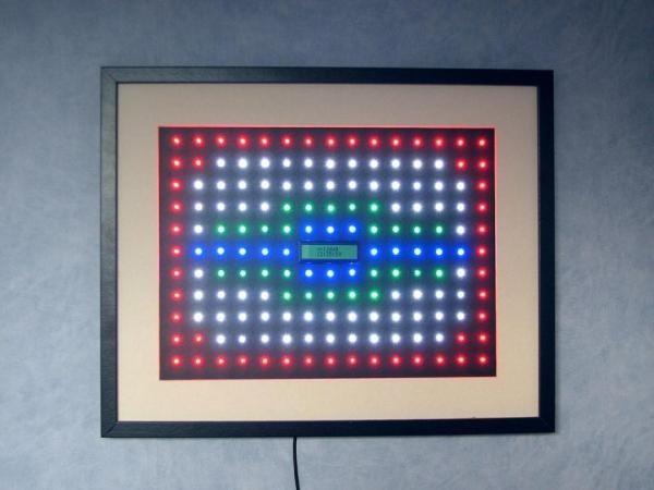
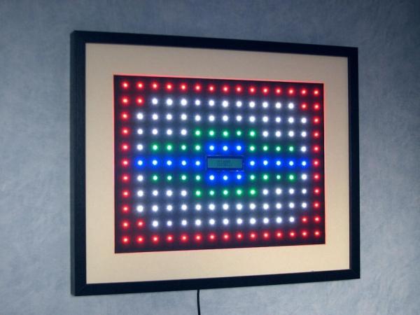
My wakeup light uses four colours, white, red, blue and green. First
come the white leds, then come red ones, and last a few blue and green leds. My idea was that I could simulate not only the increase of brightness but also the shifting of the morning light colour, by starting with a bit of white, adding in red a bit later and mixing in blue and green in the end. I’m not sure that it actually does resemble actual morning light, but I like the colourful display as it is now.
Mine is also faster than the Philips wakeup light, instead of the 30 minutes of the Philips light, mine goes from 0% to 100% brightness in less than 5 minutes. So my sun rises much faster.
NOTE:
It is VERY hard to make pictures of my wakeup light, I tried with several camera’s and smartphones but all pictures I made do not do the real thing justice.
Step 3: Sigmoid Curve, Flickering and “resolution”
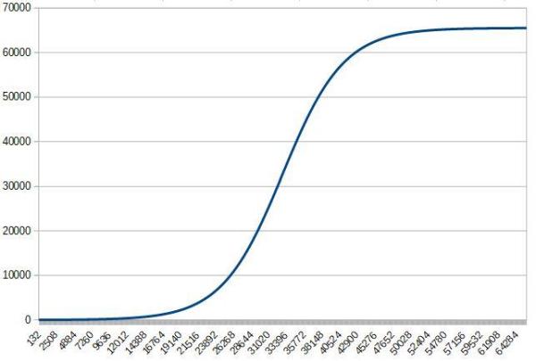
Of course I wanted to make the brightening as smooth as possible. Human eyes are logarithmic in sensitivity, meaning that in total darkness they are more sensitive than they are in full daylight. A very small increase in brightness when the levels are low “feels” the same as a much bigger step when the light is at say 40% brightness. To achieve this I used a special curve called Sigmoid (or S-curve) this curve starts as an exponential curve that halfway levels off again. I found that it is a very nice way of increasing (and decreasing) the intensity.
The clock frequency of the microcontroller (and the timers) is 16 MHz
and I use the maximum resolution of TIMER2 (65536) to create three pulse width signals (PWM). Therefore pulses come 16000000 / 65536 = 244 times per second. That is far above the limit of the eyes to see any flickering.
So the leds are fed with a PWM signal that is made with this 16 bit
timer of the STM8S103 microcontroller. At minimum this PWM signal can be ON is 1 pulse length long and the remaining 65535 pulse lengths off.
So the leds connected to that PM signal will then be ON 1/65536-th of the time: 0.0015%
At the maximum they are ON 65536/65536-th of the time: 100%.
Step 4: Electronics

Microcontroller
The brain of the wakeup light is a STM8S103 microcontroller from STMicroelectronics. I like to use parts that have just enough capabilities for a job. For a simple task as this it isn’t neccessary to use STM32 microcontrollers (my other favorites) but an Arduino UNO wasn’t enough as I wanted three PWM signals with 16 bit resolution and there is no timer with three output channels on an UNO.
Realtime Clock
The time is read from a DS1307 real time clock that works with a 32768 Hz crystal and has a 3V backup battery.
Setting of the current time, day and the wakeup time is done with two buttons and shown of a 16 x 2 LCD character display. To keep my bedroom really dark at night, the backlight of the LCD display is switched on only when the leds are brighter than the backlight and when you are setting the time, day and wakeup time.
Power
Power comes from an old laptop power supply, mine produces 12V and
can deliver 3A. When you have another power supply it may be necessary to adjust the resistors in series with the led-strings. (See below)
Leds
The leds are connected to the 12V supply, the rest of the electronics
works on 5V made with a 7805 linear regulator. In the schematic it says that I use a TO220 regulator, that isn’t needed as the microcontroller, display and real time clock use just a few milliamps. My clock uses a smaller TO92 version of the 7805 capable of supplying 150mA.
The switching of the led-strings is done with N-channel MOSFETs. Again, in the schematic it shows other devices than I used. I happened to have exactly three very old BUZ11 MOSFETs instead of the newer IRLZ34N MOSFETs. They work fine
.
Of course you can put in as many leds as you like, as long as the MOSFETs and the powersupply can handle the current. In the schematic I have drawn just one string of any colour, in reality there are several each colour parallel to the other strings of that colour.
Step 5: Resistors (for the Leds)
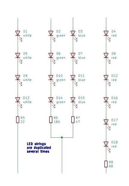
About the resistors in the led strings.
White and blue leds usually have a voltage of 2.8V over them when they are at full brightness.
Red leds have just 1.8V, my green leds have 2V over them at full brightness.
Another thing is that their full brightness isn’t the same. So it took some experimenting to make them equally bright (to my eyes). By making the leds equally bright at full brightness, they will also look equally bright at lower levels, the pulse width signal always switches them on at full brighness but during longer and shorter times, your eyes take care of the averaging.
Begin with a calculation like this. The power supply delivers (in my case) 12V.
Four white leds in series need 4 x 2.8V = 11.2V, this leaves 0.8V for the resistor.
I had found that they were bright enough at 30mA so the resistor needs to be:
0.8 / 0.03 = 26.6 ohm. In the schematic you see that I put in a 22 ohm resistor, making the leds just a little bit brighter.
The blue leds were too bright at 30mA, but compared nice to the white leds at 15 mA, they also had about 2.8V over them at 15mA so the calculation was 4 x 2.8V = 11.2V again leaving 0.8V
0.8 / 0.015 = 53.3 ohm so I chose a 47 ohm resistor.
My red leds also need some 15 mA te be equally bright as the others, but they only have 1.8V over them at that current. So I could put more in series and still have some “room” for the resistor.
Six red leds gave me 6 x 1.8 = 10.8V, so over the resistor was 12 – 10.8 = 1.2V
1.2 / 0.015 = 80 ohm, I made it into 68 ohm. Just as the others, a tiny bit brighter.
The green leds I used are as bright as the others at about 20mA. I needed just a few (just as the blue ones) and I chose to put four in series. At 20mA they have 2,1V over them, giving 3 x 2.1 = 8.4V
12 – 8.4 = 3.6V for the resistor. And 3.6 / 0.02 = 180 ohm.
If you build this wakeup light it is unlikely that you have the same power supply, you will have to adjust the number of leds in series and the resistors needed.
A small example. Say you have a powersupply that gives 20V. I would chose to set 6 blue (and white) leds in series, 6 x 3V = 18V so 2V for the resistor. And lets say you like the brightness at 40mA. The resistor then needs to be 2V / 0.04 = 50 ohm, a 47 ohm resistor will be fine.
I advise not to go any higher than 50mA with ordinary (5mm) leds. Some can handle more, but I like to be on the safe side.
Step 6: Software
All the code can be downloaded from:
https://gitlab.com/WilkoL/wakeup_light_stm8s103
keep the source code open, next to the rest of this instructable if you want to follow the explanation.
Main.c
Main.c first sets up the clock, timers and other peripherals. Most of the “drivers” I wrote using the Standard Library from STMicroelectronics and if you have any questions about them, write it in a comment below the instructable.
Eeprom
I left the “text to display” code that I used to put texts in the eeprom of the STM8S103 as comments. I wasn’t sure that I had enough flash memory for all my code so I tried to put as much as possible in eeprom to have all flash for the program. In the end that proved not necessary and I moved the text to flash. But I left it as commented out text in the main.c file. It is nice to have it, when I need to do something similar later (in another project)
The eeprom is still used, but only for storing the wakeup-time.
Once a second
After setting up the peripherals the code checks if one second has passed (done with a timer).
Menu
If that is the case it checks if a button was pressed, if so it enters the menu where you can set the current time, the day of the week and the wakeup time. Remember that it takes about 5 minutes to go from off to full brightness, so set the wakeup time a bit earlier.
The wakeup time is stored in eeprom so that even after a power outage it will “know” when to wake you. The current time is stored in the real time clock of course.
Comparison current & wakeup time
When no button was pressed it checks the current time and compares it with the wakeup time and weekday. I don’t want it to wake me in the weekend 🙂
Most of the time nothing needs to be done so it sets the variable “leds” to OFF else to ON. This variable is checked together with the “change_intensity” signal, that is also coming from a timer and is active 244 times per second. So when the “leds” variable is ON the intensity is increased 244 times per second and when it is OFF is decreases 244 times per second. But the increase goes in single steps where the decrease is in steps of 16 meaning that when the wakeup light has hopefully done its job, it turns off 16 times faster but still smoothly.
Smoothness and OUT OF MEMORY
The smoothness comes from the Sigmoid curve calculation. The calculation is quite simple but it needs to be done in floating point variables (doubles) because of the exp() function, see the file sigmoid.c.
In the standard situation the Cosmic compiler / linker does not have support for floating point variables. Switching it on is easy (once you have found it) but is comes with an increase in code size. This increase was too much to make the code fit in flash memory when combined with the sprintf() function. And that function is needed for converting numbers into text for the display.
Itoa()
To remedy this problem I created the itoa() function. This is a Integer To Ascii function that is rather common, but not included with the STMicroelectronics standard library, nor with the Cosmic libraries.
Source: Wakeup Light