In this tutorial I’m going to show you how to make a remote to control your Canon DSLR camera.
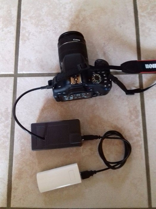
The remote is connected to your camera via the 2.5mm stereo connector. This will only control the shutter and the focus. Other parameters need to be set manually.
I used an Arduino Mega with a wifi shield, but any microcontroller with at least 2 digital outputs and connected to wifi will do the trick.
To control the Arduino, I use the Blynk app installed on my phone. This allows me to manually control the shutter and the focus, and it also allows me to program the Arduino to take a picture every x seconds for a determined period, which in the end makes a timelapse video, a feature that was not included in my Canon model.
Step 1: Build It
In summary this is how it works:
- The Blynk app sends commands to the Blynk server via wifi (or mobile broadband if your phone is not connected to the wifi).
- The commands are sent from the Blynk server to your device (for example Arduino Mega) via wifi. Your Arduino device needs to be in a wifi range.
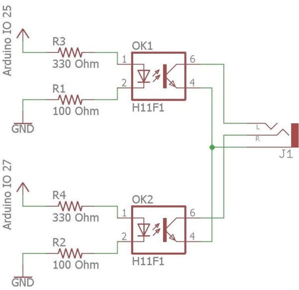
- The Arduino sends 5V to DO 25 to open the shutter (or DO 27 to do the focus).
- 5V is reduced to 1.2V using 2 resistors.
- When 1.2V is applied to one of the 2 optocouplers, it will short the shutter (or focus) input of the camera to the ground, and take a picture (or do the focus).
To convert 5V to 1.2V, a 100Ohm and a 330Ohm resistors were used as shown in the scheme.
Optocouplers were used in order for the camera to be isolated from the Arduino: in case anything goes wrong with the Arduino, it won’t damage the camera.
The circuit was soldered on a solderable breadboard that can be found on sparkfun: www.sparkfun.com
The breadboard is plugged in the Arduino: 3 male/male pins are simply soldered below the board, and these pins are inserted in the ground, digital input 25 and digital input 27 of the Arduino.
The 2.5mm stereo jack can be found on sparkfun: www.sparkfun.com
The optocouplers are very simple ones that use 1.2V, found on Distrelec: www.distrelec.ch
Step 2: Program the Arduino
No particular difficulties here. The Arduino was programmed using the Arduino IDE. Note that it can connect to a list of 2 wifi SSID / passwords. This list can easily be expanded.
The code can be found on GitHub:
https://github.com/vjuvet/wifi-camera-remote
Step 3: Set Up Blynk
3 tabs have been created in this Blynk project:
- Manual is used to manually trigger the shutter or the focus
- Auto is used to start the timelapse and set its parameters
- Terminal is used to verify when the shutter has effectively been triggered.
Manual tab:
A button widget directly controls digital pin 25 (for the shutter). It goes from 0 (off) to 1 (on).
An led widget is linked to virtual pin V1. It is used as a feedback and is lit when output 25 is high.
The same is done for the focus, with pin 27 instead of 25 and V2 instead of V1.
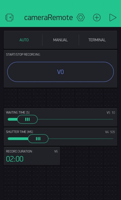
Auto tab:
A button widget is linked to virtual pin V0 and is used to start / stop the recording
2 Slider widgets are linked to virtual pins V4 and V5 and are used to send the time that the shutter contact has to be closed to take a picture, and the time between each picture, respectively.
A time input widget is linked to virtual pin V6 and sends the duration of the recording.
Terminal:
A terminal widget is used to send informations to the user. It is linked to pin V3. Here I’m just showing when the shutter is effectively opened, to verify that the picture is really taken every V5 seconds.
Notes:
- In autofocus mode, the focus does not need to be done to take a picture. On my model (eos 750d), the focus is automatically done before taking a picture, even if the focus contact is not shorted to ground. The shutter contact will therefore need to be made for at least 500ms (V4) to let the camera do the focus, or the picture won’t be triggered.
- In manual focus mode, the picture is taken more quickly, so the shutter contact can be lowered to 200ms (V4). These values depend on your camera model.
- The time that the contacts are effectively shorted is very precise, I measured an error of maximum 1ms, with V4 varying between 3ms and 2000ms.
- This system cannot be used to control the time the shutter is open by setting the camera on bulb mode: I measured variations of up to 200ms in the shutter speed when using bulb mode, which is a lot and greatly affects the picture.
Step 4: Use It
The downside of this system is that the device needs to be in the range of a wifi to work. If you want to use it outside, a workaround is to create a wifi with your smartphone so that the device can connect to it.
Once the series of pictures is taken, there is a variety of softwares available to convert them to a film. I found the Gopro software handy, easy to use and free.
To supply power to the Arduino, the easiest way is to use an external battery for smartphones. It lasts longer, can be recharged, and supplies a constant 5.0V.
The above video was made by taking a picture every 10 seconds (V5) for 2 hours (V6).
Once this is done, adding a sensor to the Arduino to take a picture at a particular time is really easy. One can for example add a motion detector to take a picture when something moves, a photoresistor to take pictures of lightnings, or a microphone to take a picture when you clap your hands, etc…
Have fun!
Source: Wifi Camera Remote