Summary of WiFi Controlled Camera Slider
This article details the construction of a DIY motorized camera slider, referred to as Camera Slider MK4. The project utilizes 3D printed components alongside standard electrical and mechanical hardware to create a WiFi-controlled device. By using a Particle Photon microcontroller and an EasyDriver stepper driver, users can control the slider via a custom Android application called Bestir. This approach offers a cost-effective alternative to commercial motorized sliders while providing smooth motion effects for video production through precise step control and microstepping capabilities.
Parts used in the Camera Slider MK4:
- Particle Photon WiFi development board
- EasyDriver Stepper motor driver board
- NEMA 17 stepper motor
- 12V power supply
- R-78E3.3-1.0 Switching Voltage Regulator
- Breadboard
- Jumper Wires
- 2.1mm DC Barrel Jack
- 500mm linear slide rail
- Linear bearing pillow block
- 610mm aluminum extrusion
- GT2 timing belt
- GT2 Timing belt pulley
- 608zz ball bearing
- Camera ball mount
- M3 x 6mm screws
- M4 x 8mm screws
- M4 x 18mm screws
- M4 nuts
- M5 x 16mm screws
- M4 T-Nuts
- 1/4" screw with D-ring
If you want to add interest to any video you are making, a good way to doing it is to add motion. There are an infinite number of motion effects you could use in your videos, but a classic, and very pleasing one, is a sliding effect. You will see this effect used in numerous videos in which the camera smoothly slides across the frame.
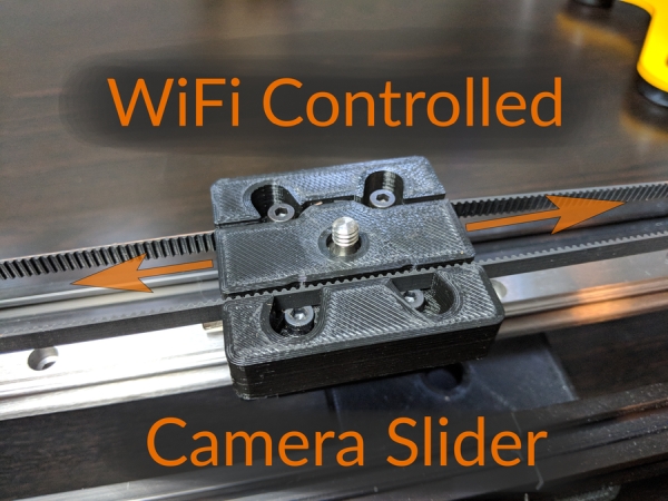
Producing shots like these requires a bit of hardware. A camera slider consists of a rail across which a camera smoothly slides. For more controlled motion, many camera sliders use a motor. However, for such a seemingly simple device, camera sliders can cost a bit chunk of money.
That’s why, in this Instructable, we will be building our own motorized camera slider. The slider will use 3D printed parts and off-the-shelf components. The slider will be controlled via WiFi using a bespoke application. The cost for this whole project will be a fraction of what it would cost to buy a motorized camera slider at retail.
Step 1: Gather Your Parts
Many of the parts used to build the Camera Slider MK4 are produced via 3D printing and those parts are discussed in the next step. However, in addition to the 3D printed parts, we will also need the electrical and mechanical hardware below to complete the build.
Since much of this build is very similar to the Adafruit Motorized Camera Slider MK3, the parts list is similar as well. The microcontroller and stepper motor driver used in this Instructable are different and a few of the mechanical components have been replaced with different ones as well.
Electrical Parts
1 x Particle Photon
WiFi development board
1 x EasyDriver
Stepper motor driver board
1 x NEMA 17 stepper motor
For moving the sliderM/span>
1 x 12V power supply
Powers the electronics and the motor
1 x R-78E3.3-1.0 Switching Voltage Regulator
The explanation for this part is a little involved.
More details will be provided when we start assembling the electronics.
1 x Breadboard
For easily connecting everything together
1 x Jumper Wires
For doing the actual connecting
1 x 2.1mm DC Barrel Jack
For connecting the power supply
Mechanical Parts
1 x 500mm linear slide rail
Fully supported linear motion rail
1 x Linear bearing pillow block*
This part slides on the rail
2 x 610mm aluminum extrusion
Provides structural support
1 x GT2 timing belt
Allows the motor to drive the camera mount
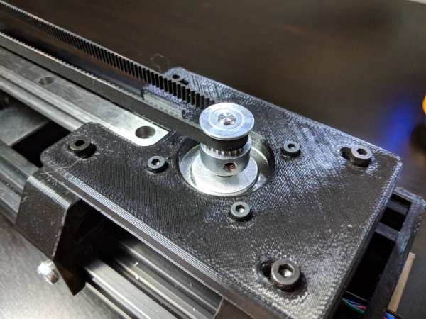
1 x GT2 Timing belt pulley
Mounts onto the motor to drive the belt
1 x 608zz ball bearing
Supports the side of the belt opposite the motor
1 x Camera ball mount
For holding the camera
* Adafruit carries two different pillow blocks. Having used these for several projects, I have found that Adafruit is often out of stock on one or the other pillow block. Therefore, the 3D printed mounting plate in the next step is designed to use either of the pillow blocks: the narrow 15mm pillow block or the wider pillow block.
Fasteners
1 x Package M3 x 6mm screws
For mounting the motor
1 x Package M4 x 8mm screws
For attaching various parts
1 x Package M4 x 18mm screws
For attaching various parts
1 x Package M4 nuts
For putting onto the M4 screws
1 x Package M5 x 16mm screws
For the pillow block
1 x Package M4 T-Nuts
For mounting things to the aluminum extrusions
1 x 1/4″ screw with D-ring
Standard screw for camera tripod mounts
Step 2: 3D Printed Parts
All the parts not listed in the previous step are 3D printable with FDM 3D printers. The type of material used is not particularly important. All the parts in this Instructable were printed with PLA. If you want more strength, the parts can also be printed in ABS or other high-strength materials. All of the parts, and other files used throughout this Instructable are available in a GitHub repository.
What if I don’t have a 3D printer?
Even if you don’t own a 3D printer, you can still certainly complete this project. 3D Hubs is a great platform that allows you do get your 3D printed parts made by local 3D printer operators in your area. I’ve used 3D Hubs for dozens of projects and I would highly recommend the service.
Dry Fit Testing
Before you start building the camera slider, it is a good idea to test the fit and tolerances of your 3D printed parts. This could potentially save a lot of headache later on. Of particular importance is making sure that the screws fit into the screw holes on the 3D printed parts. If the holes are a little too snug for the screws to fit properly, you can risk breaking the 3D printing part by trying to force the screws to fit. Instead, use a drill to widen the holes with an appropriately-sized bit.
Step 3: Assemble the Camera Slider
With all the purchased parts purchased and the printed parts printed, it is time to assemble the camera slider. The process of assembling the slider in this Instructable is, with the exception of the controller electronics, the same as the Adafruit Motorized Camera Slider MK3 tutorial. So, go over to the Adafruit Learn side and follow the directions for assembling the hardware. Just skip any steps related to the electronics:
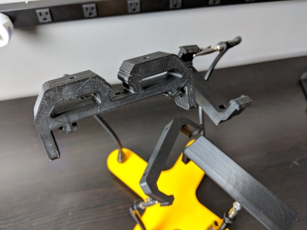
Stepper Motor Assembly: the only difference in this step between the Adafruit tutorial and this Instructable is that the stepper motor support part is taller in our MK4 version.
Bearing Mount Assembly: as with the stepper motor support, the bearing support used in this Instructable is also taller than the one used in the Adafruit tutorial
Tripod Mount Assembly: this step exactly matches this Instructable
Extrusion Assembly: aside from the supports being taller than in the original version, putting the sub-assemblies together uses the same process as the Adafruit tutorial
Case Assembly: skip this step because both the electronics enclosure and the actual electronics are completely different in this Instructable versus the Adafruit tutorial. We will cover the electronics assembly in the next few steps.
Camera Mount Assembly: mounting the camera mount onto the slider platform is the same in the Adafruit tutorial as it is in this Instructable. The geometry of the slider platform used in this project is different because it is designed to use either version of the pillow block part available from Adafruit.
Rail Assembly: follow the Adafruit tutorial to mount the rail
Belt Assembly: adding the belt to the slider assembly is a little bit tricky but the process shown in the Adafruit tutorial is the same as the one used in this Instructable
Final Assembly: this step shows how to add the final couple mechanical parts to the slider
Step 4: Attach the Electronics Enclosure
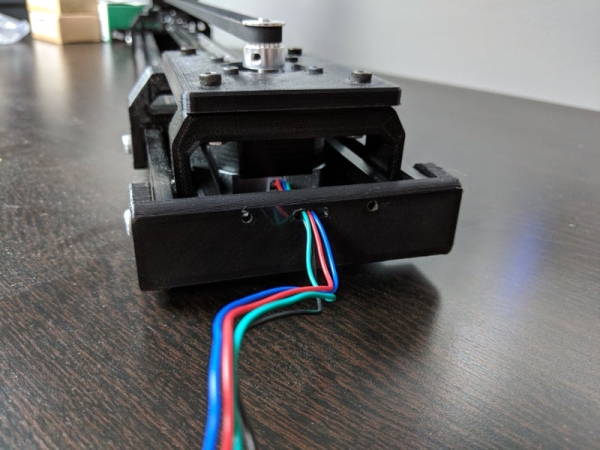
In a short while, we will be using a half-size breadboard to assemble all of the electronics used to build our WiFi camera slider controller. For this reason, the case used to hold the electronics for this Instructable is larger than the one in the Adafruit tutorial, which is only designed to accommodate a Metro board.
By this point, your camera slider should be fully assembled, except that it is missing any of the electronics besides the motor. The electronics enclosure mounts onto the side of the camera slider that also houses the motor; you should have the cables for the motor coming out of this side. Attach the electronics enclosure using two M4 x 10mm screws and matching nuts. The screws will protrude from the bar-mount-left.stlpart. The nuts will go inside the electronics enclosure.
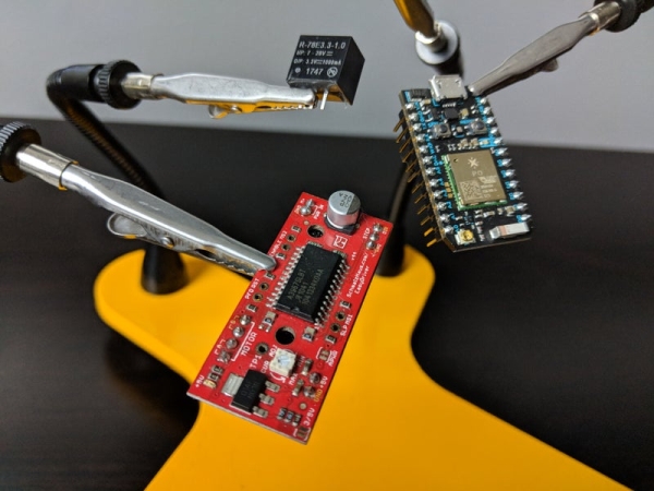
Step 5: Prepare the EasyDriver
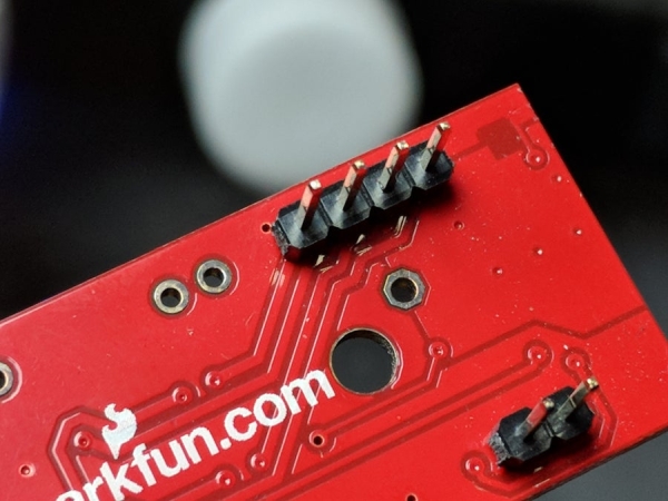
Before we can start assembling the electronics, we need to get the EasyDriver ready. Unlike the Particle Photon that came with male headers pre-installed, we will need to solder headers onto the EasyDriver so it can be connected to the breadboard. Simply solder male pin headers onto all the positions around the periphery of the board.
Step 6: Mount Photon, EasyDriver, and Voltage Regulator to Breadboard
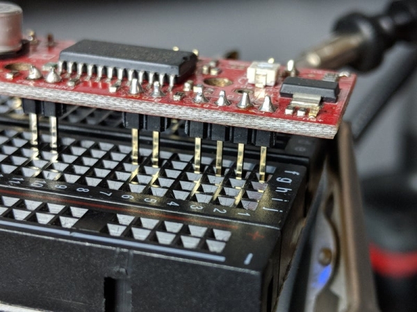
Now that the EasyDriver is equipped with headers we can mount it, along with the Particle Photon and the switching voltage regulator, onto the breadboard. In the following step we will wire the components together.
Fitting all of the parts on the breadboard will be a tight fit. First, place the EasyDriver onto the breadboard with the voltage regulator towards the end of the breadboard. Position the EasyDriver as far as it can go on one side of the breadboard. The end of the board itself will actually overhand the breadboard a bit.
The Particle Photon will mount onto the opposite side of the board. The breadboard should be just long enough to accommodate both the Particle Photon and the EasyDriver.
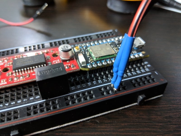
The trickiest part is placing the DC/DC converter onto the breadboard. On the side of the EasyDriver opposite the connections for the motor, you will notice a gap between the two sets of pins positioned in either corner of the board. We will take advantage of the absence of pins in this area to add the DC/DC converter to the breadboard. Plug the regulator into the breadboard in the row of pins closest to the power rail. There should be a gap just big enough between the EasyDriver and the DC/DC converter to add wires later on.
Why are we using the DC/DC converter?
We have a couple things going on with the power system in this design. First of all, the entire camera slider is powered from a 12V 2A power supply. The stepper motor is by far the most power-hungry component in this build. It can consume up to 1A all on its own. So, we need this relatively beefy power supply to feed the stepper motor.
The EasyDriver board is powered from this same power supply. The tricky bit is powering the Particle Photon. The Particle Photon runs on only 3.3V. Therefore, in order to avoid releasing the blue smoke from the Particle Photon, we need to step down the 12V power supply to 3.3V.
The EasyDriver actually has an on-board voltage regulator. There is even a jumper in one corner of the board for selecting a 3.3V output from the GND/5V pins right next to it. The issue is that stepping down 12V to 3.3V is too much power dissipation for this little linear regulator to handle and it will overheat. If you ever see your Particle Photon doing something like in the animation below, the regulator you are using to supply the Photon is overheating.
Fortunately there is a solution to this issue. The problem with using a linear voltage regulator is that they convert voltage by simply dumping the excess power as heat. If you try to put too much power through a linear voltage regulator it will overheat and shut down, like the above video shows.
Therefore, instead of using a linear voltage regulator, we will use a different kind of regulator called a switching regulator, which is also called a DC/DC converter. Switching regulators are able to change a voltage level while generating significantly less heat. Switching regulators are wired essentially the same way as a linear regulator. A high voltage goes in one side and a lower voltage comes out the other side, with ground connection in the middle.
Step 7: Wire the Breadboard
With the major parts of the controller attached to the breadboard, now we need to attach everything together electrically.
Let’s start with the power system.
Power System Wiring
We will start connecting all the parts by wiring the electrical system. First connect the DC barrel jack pigtail to one of the power rails on the side of the breadboard. From that connection, the power will branch into two paths. One will power the EasyDriver and stepper motor, the other will power the Particle Photon via the DC/DC converter discussed in the previous step.
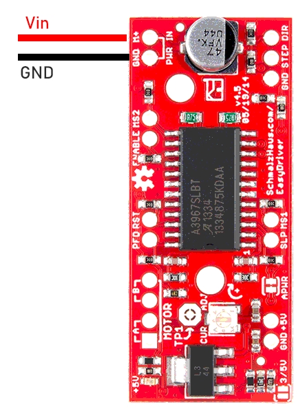
Connect the GND power rail on the breadboard to the GND connection on the EasyDriver. Then, connect the positive power rail on the breadboard to the M+ pin on the EasyDriver.
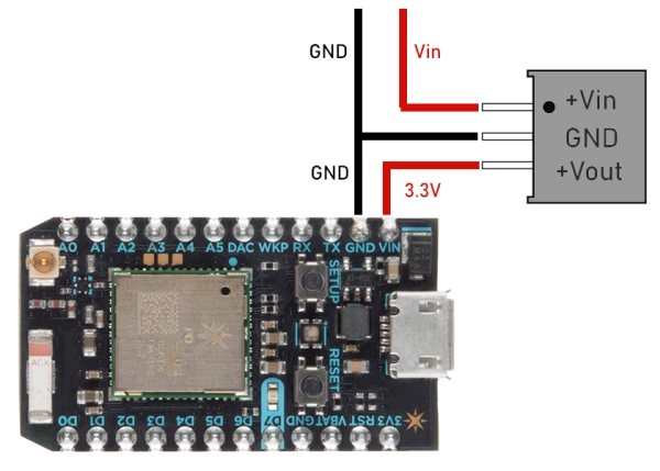
For the Particle Photon, first connect the GND power rail on the breadboard to the GND pin on the Photon. Next, connect the GND power rail on the breadboard to the middle pin on the DC/DC converter. If you take a look at the DC/DC converter, you will find a small dot on one corner. Connect the pin below this dot to the positive power rail on the breadboard. Finally, connect the last pin on the DC/DC converter, the one opposite the dot, to the Vin pin on the Particle Photon.
Control Wiring
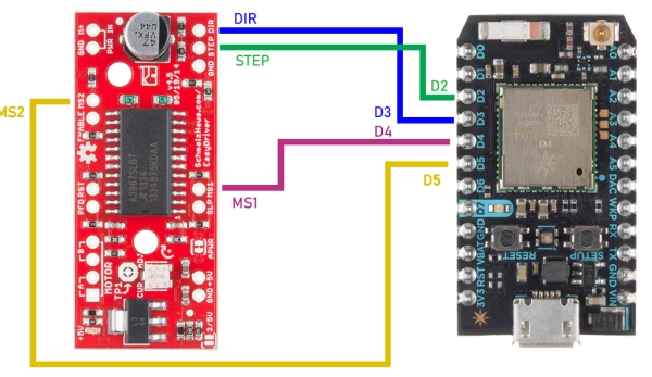
Next we will connect the Particle Photon and the EasyDriver together. Follow the table below to connect the two boards.
| EasyDriver | Particle Photon |
|---|---|
| MS1 | D4 |
| STEP | D2 |
| DIR | D3 |
| MS2 | D5 |
What do the control pins do?
The Particle Photon and the EasyDriver communicate over four connections, the wires we just connected. The MS1 and MS2 connections work together to set the microstepping resolution of the EasyDriver. In our camera slider, we will use 1/16 microstepping most of the time because it will yield the smoothest motion. So, the MS1 and MS2 pins will be simply set to HIGH by default.
The DIR pin determines in which direction the stepper motor moves. By pulling this pin HIGH or LOW, the motor will switch direction. You will find more information about the direction of movement when we get to flashing software on the Particle Photon soon.
Finally, the STEP pin triggers a single step of the stepper motor. The size of this step is determined by the microstepping resolution. Each time this pin goes from LOW to HIGH, a step is triggered. This pin will get further explanation in the step discussing the software.
Motor Wiring
Attaching the motor is easy. In one corner of the EasyDriver there are four pins. Two are labeled A and two are labeled B. Your stepper motor has four wires. Inside the motor there are two different coils and two wires attached to each. Identifying the coils is easy using a multimeter. Attach one coil pair to the A pins and the other to the B pins.
Step 8: Add Breadboard to the Electronics Enclosure
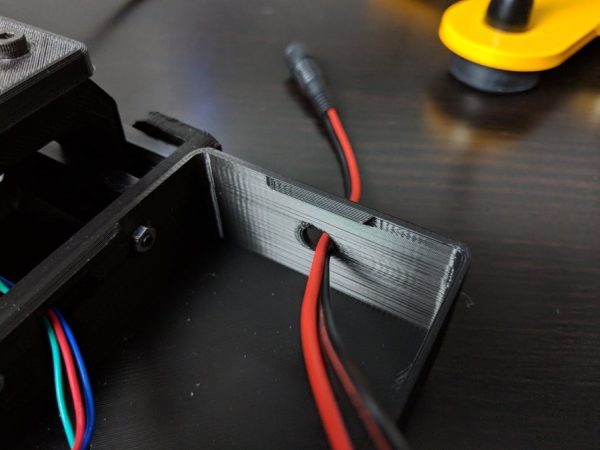
Now that the electrical system has been assembled, we can install it into the electronics enclosure. This step is an easy one. First, run the DC barrel jack through the hole in the side of the enclosure. Then, place the breadboard, with all of its components and wiring attached, into the enclosure. Finally, place the lid on the enclosure. When placing the lid onto the enclosure, be careful not to dislodge any of the wires. The lid attaches to the enclosure using simply snap fittings.
Step 9: Add the Particle Photon to Your Particle Account
At this point we are all done assembling the WiFi Controlled Camera Slider hardware. Good work so far! Over the next couple steps we will work on programming the Particle Photon with the firmware necessary to run the camera slider.
However, before you can program your Particle Photon, or issue it commands after flashing its firmware, you will need to add the Photon to your Particle account. That’s what we’ll do in this step. I use Android devices myself, so the steps in this Instructable will apply to Android phones. However, if you own an iPhone, the process is basically the same.
Add the Photon to your Particle Account
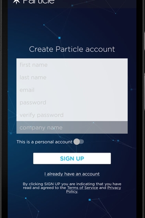
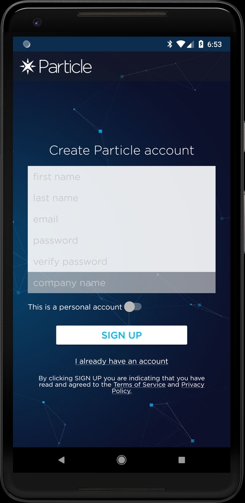
First of all, download the Particle app from the Play Store.
With the app open, first either log into your Particle account if you already have one, or register a new account if you’ve never used Particle before (if this is the case I think you will really enjoy using Particle, it is a great system).
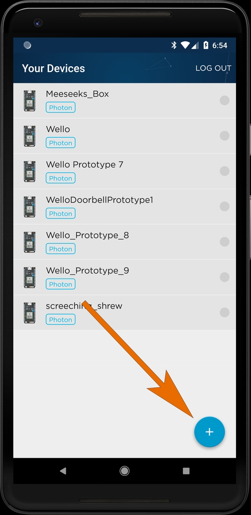
Once you get logged in, tap the + button at the bottom of the screen to add a new Particle device to your account.
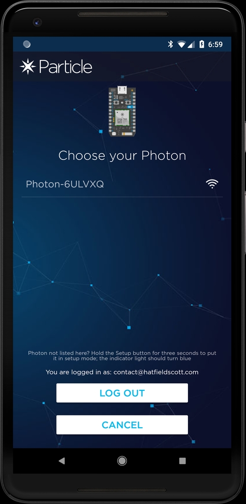
Now plug the power supply into the DC barrel jack to power on the Particle Photon inside your camera slider. Give the Photon a couple seconds to start up and then press the Ready button. The Particle app will begin searching for your Photon. Once your Photon appears in the list, tap it to begin setup.
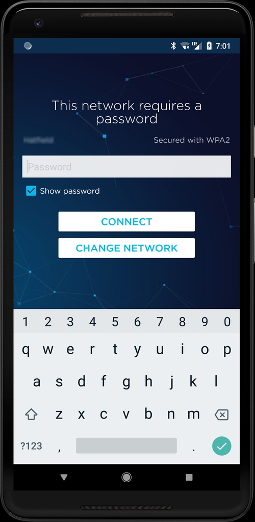
You will need to get the Photon connected to your WiFi network. The app will scan for available WiFi networks. Choose your WiFi from the list and supply the password.
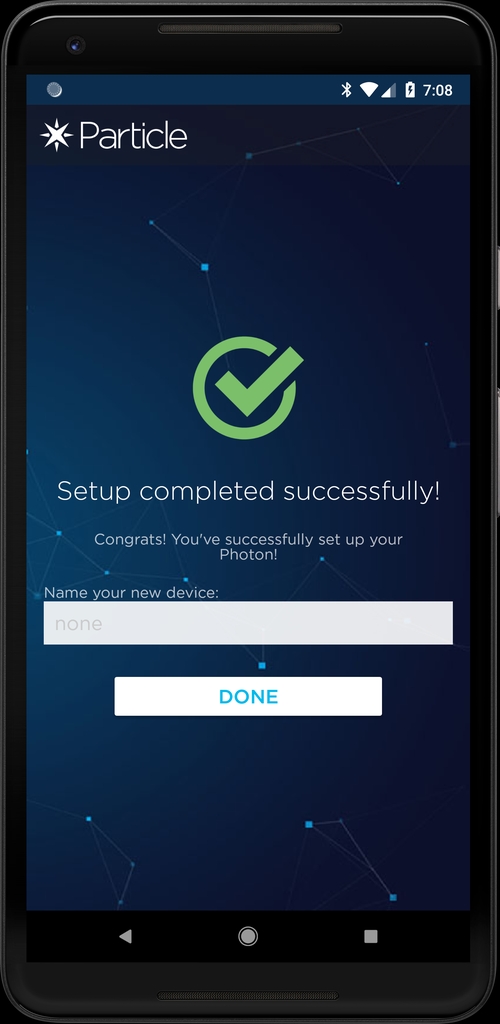
Once the Particle Photon connects to your WiFi network, the only thing left to do is give your Photon a name.
Step 10: Flash Firmware Onto the Particle Photon

Now that the Particle Photon inside your camera slider has been added to your Particle account, you can flash the firmware onto the controller. Particle uses an online IDE for developing Photon firmware and sending it to your Particle devices. You don’t even need to plug the Particle Photon into your computer like you do with most microcontrollers. This will be especially useful for this project since the Photon is now sealed inside the camera slider electronics enclosure. Head over to the Particle Cloud IDE.
You can find the firmware for this project in the GitHub repository. Grab the code and copy/paste it into the Particle IDE.
In the Particle IDE, we need to select the newly added Photon as the target device on which to flash the firmware. To do this, click the target ridicule icon in the menu on the left side. Each of your Particle devices in the list has a small star next to it. Click the star for the Photon you just added to your account.
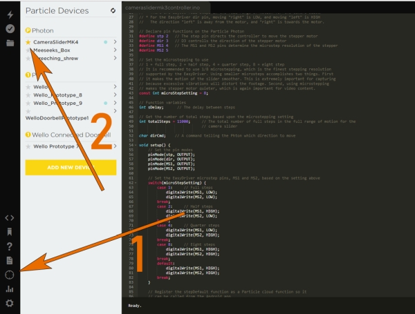
With your Photon selected, click the Flash button, which is the lighting bolt icon in the upper-left corner of the screen. The firmware should take just a few moments to flash onto the Photon.
Dissecting the Firmware
If you don’t care much about how the firmware actually works and just want to get to shooting video, feel free to skip this step and move on to the next one. However, if you are interesting in knowing how the firmware works, this section will explain everything.
Let’s start at the top. The firmware for the Particle Photon inside the camera slider begins like most Arduino sketches you may have worked on in the past, by defining the pin connections.
// Declare pin functions on the Particle Photon #define stp 2 // The step pin directs the controller to move the stepper motor #define dir 3 // D3 controlls the direction of the stepper motor #define MS1 4 // The MS1 and MS2 pins determine the microstep resolution of the stepper #define MS2 5
The function of each pin was discussed in a previous step. The stp (STEP pin on the EasyDriver) is used to trigger the stepper motor to move, one step at a time. Each time the stp pin goes from HIGH to LOW, the stepper motor moves by one step. So, as we will see later in this explanatory section, the Photon moves the stepper motor by flipping the stp pin from LOW to HIGH, many, many times, very quickly.
The dir pin controls in which direction the stepper motor moves. For the purposes of this project, the direction “left” is moving away from the electronics enclosure and “right” is moving towards the enclosure. When the dirpin is set to HIGH, the slider will move towards the electronics, and when it is set to LOW, the slider will move away from the motor.
The MS1 and MS2 pins are both used to adjust the microstepping resolution of the EasyDriver. Depending upon the combination of these two pins being set to HIGH or LOW, the EasyDriver can use full, 1/2, 1/4, or 1/8 microstepping.
| MS1 | MS2 | Microstep Resolution |
|---|---|---|
| LOW | LOW | Full Step |
| HIGH | LOW | Half step |
| LOW | HIGH | Quarter step |
| HIGH | HIGH | Eight step |
Speaking of microstepping resolution, the next line of the code defines the microstepping resolution to be used by the firmware.
const int microStepSetting = 8;
Unless you need the slider to move very quickly, most of the time it is recommended to use 1/8 microstepping. The larger the microstepping resolution, the larger the individual steps are. Because the camera slider will be used for recording video most of the time, the downside to using larger steps is that they produce more vibration, which can be noticeable in the video.
The next configuration option is the total number of full steps required to traverse the length of the camera slider. For the design used in this Instructable, it takes 11,000 full steps to move the sliding plate fully across the slider. The modular design of the slider in this Instructable can be easily adapted for a longer slider, in which case a larger number of steps will be required.
int totalSteps = 11000;
In the setup function, after defining the function of the pins, there is a switch/case statement for setting the microstepping resolution based on the configuration option above. The statement sets the MS1 and MS2 pins as described in the truth table above.
// Set the EasyDriver microstep pins, MS1 and MS2, based on the setting above switch(microStepSetting) { case 1: // Full steps digitalWrite(MS1, LOW); digitalWrite(MS2, LOW); break; case 2: // Half steps digitalWrite(MS1, HIGH); digitalWrite(MS2, LOW); break; case 4: // Quarter steps digitalWrite(MS1, LOW); digitalWrite(MS2, HIGH); break; case 8: // Eight steps digitalWrite(MS1, HIGH); digitalWrite(MS2, HIGH); break; default: digitalWrite(MS1, HIGH); digitalWrite(MS2, HIGH); break;
There is one other, very important line in the setup function that will make the most sense to revisit later.
This firmware is a little different than most because there is nothing whatsoever in the loop function.
void loop() { // Nothing to do here }
The next function in the firmware is used to set the dir pin. This is a simple function that just sets the dir pin either to HIGH or to LOW.
// Set the direction of movement void setDirection(char dirCmd) { if(dirCmd == 'r') { // Right moves towards the motor digitalWrite(dir, HIGH); } else { // Left moves away from the motor digitalWrite(dir, LOW); } }
Next up, we have the function that is mostly responsible for the work done by the firmware. This function makes use of one powerful feature offered by the Particle ecosystem, Cloud Functions. The Particle ecosystem enables firmware to be written with functions that are exposed to the cloud so they can be called from other devices. For the purposes of this project, we will be calling this cloud function from the Android application (more on that later).
Let’s get back to that line we skipped over in the setup function earlier.
bool success = Particle.function("stepKey", stepDefault);
This line exposes the stepDefault function to the Particle cloud so it can be called from the Android app. Let’s discuss the function itself.
int stepDefault(String command) { // First, extract the direction from the command dirCmd = command.charAt(0); setDirection(dirCmd); // Set the travel direction // Second, extract the step delay String sDelayStr = command.substring(1); sDelay = (sDelayStr.toInt()) / microStepSetting; // There are 11000 steps total for full steps. Loop through // 11000 times to travel all the way across the slider. for(int i = 0; i < totalSteps; i++) { digitalWrite(stp,HIGH); // Trigger one step forward delay(1); digitalWrite(stp,LOW); // Pull step pin low so it can be triggered again delay(sDelay); } return sDelay; }
This function receives an argument from the Android application, the argument contains information about which direction to move the slider, and how long to delay between steps. The direction command is either “r” or “l” which is set by the Android app.
The next part of the argument is the delay between steps. This value is calculated by the Android application. The user provides a total time for the duration of the slide. By diving this value by the total number of steps, multiplied by the microstepping resolution, a delay between steps is calculated.
To actually move the motor, the Particle Photon flips the stp pin between LOW and HIGH numerous times, very quickly. Each time the stp pin goes from LOW to HIGH, the stepper motor moves by one step.
Step 11: Install the Android App
Alongside the firmware running on the Particle Photon, the other part of the codebase for this project is the Android application. The camera slider in this Instructable is controlled from a bespoke application. The application is called Bestir, a word meaning “to rouse to action, get going.”
You can download the Bestir app used to control the camera slider directly from the Google Play Store. The application is currently in Beta.
If you want, you can also find the source code for the app in the GitHub repository.
Using the App
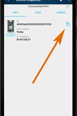
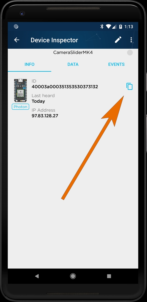
The application itself is fairly simple to use. You will need to get one piece of information before you begin: the ID of the Particle Photon inside the camera slider. To get this information, open up the Particle app again. In the list of Particle devices, select the one you added to your account earlier. The the Device Inspector you will find the ID of your Particle Photon. You don’t need to bother writing this down though, next to this long number there is a button for copying the ID to the clipboard.
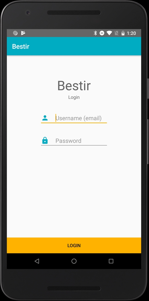
So take this copied value and open the Bestir app. The first step to using the app is logging in to your Particle account. In the Particle ecosystem you must be logged in to access cloud functions for your device which, as discussed in the previous step, is how the system works.
After logging in, you will be directed to the main part of the Bestir application. At the top of the page you will find a place to put the Photon ID we copied earlier.
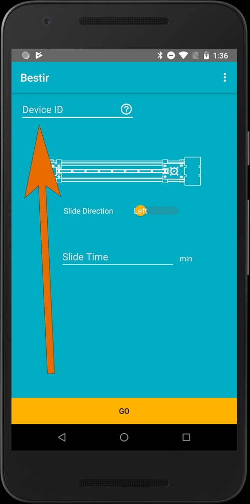
With the device ID pasted into place, using the app to control your camera slider is as simple as telling the system in which direction to move, inputting the total length of time the move will take, and pressing Go.
Source: WiFi Controlled Camera Slider
- How much does this project cost compared to buying a retail slider?
The cost for this whole project will be a fraction of what it would cost to buy a motorized camera slider at retail. - What material is recommended for 3D printing the parts?
All parts were printed with PLA, though ABS or other high-strength materials can be used for more strength. - Why is a switching voltage regulator used instead of a linear one?
A linear regulator would overheat when stepping down 12V to 3.3V, whereas a switching regulator generates significantly less heat. - How do I connect the stepper motor wires to the EasyDriver?
You must identify the two coils inside the motor using a multimeter and attach one coil pair to the A pins and the other to the B pins. - What happens if the screw holes in the 3D printed parts are too snug?
You should use a drill to widen the holes with an appropriately-sized bit to avoid breaking the part by forcing the screws. - Can I complete this project without owning a 3D printer?
Yes, you can use a platform like 3D Hubs to get your parts made by local 3D printer operators. - Which pins on the Particle Photon control the direction of the motor?
The DIR pin determines the direction; setting it HIGH moves the slider towards the electronics enclosure, while LOW moves it away. - What is the name of the Android application used to control the slider?
The bespoke application used to control the camera slider is called Bestir. - How many full steps are required to traverse the length of this specific slider design?
It takes 11,000 full steps to move the sliding plate fully across the slider for this design. - Does the firmware loop function contain any active code?
No, there is nothing whatsoever in the loop function because the work is done via cloud functions called from the app.