Summary of WIND TURBINE PHONE CHARGER
This project details a portable wind turbine phone charger delivering up to 15W via USB-C. It features a two-level Savonius vertical axis wind turbine connected to a gearbox and a permanent magnet DC generator. The system includes a SEPIC DC/DC converter for voltage regulation, an ATMEGA32 microcontroller for monitoring wind speed and displaying data on an LCD, and a battery pack for storage. The design emphasizes portability and omnidirectional wind capture.
Parts used in the Wind Turbine Phone Charger:
- Savonius Rotor (Two-level structure with offset blades)
- PVC Schedule 40 Pipe (8-inch diameter)
- Permanent Magnet DC Generator (36W motor)
- Gearbox (Fixed gear ratio of 9)
- SEPIC DC/DC Converter
- ATMEGA32-16PU Microcontroller
- LCD Display (2x16 screen)
- Tantalum Capacitors
- Push Button Reset Switch
- Battery Pack
- USB-C Interface
- Resistors (Voltage divider components)
- Crystal Oscillator (16 MHz)
Abstract
The wind turbine phone charger is designed to deliver a maximum of 15W of power to a battery pack, capable of charging various portable electronic devices via USB ports. The turbine comprises a two-level Savonius structure with offset blades to capture wind from any direction. These blades are linked to a shaft that turns a gearbox, enhancing the speed for the generator’s operation. A permanent magnet DC machine serves as the generator, producing an unregulated voltage. This voltage undergoes processing via power electronics and a USB-C interface, generating a 5V output for the battery pack. A microcontroller oversees the generator’s output, calculating wind speed based on this data. Both values—the generator output and wind speed—are showcased on an LCD display. Additionally, the microcontroller supplies 5V to several chips within the power electronics system. While each component functions properly independently, integrating all these parts poses a challenge.
1. Introduction
The use of renewable energy has been steadily increasing over the years, with solar and wind farms generating hundreds of megawatts daily. This trend extends to smaller scales, where residences employ solar panels, and even external phone batteries can be linked to solar panels. However, solar power is reliant on sunlight, and battery packs have limited storage capacity. Little exploration has been done on utilizing small-scale wind power, yet there remains high demand for portable device power supplies in the foreseeable future. The wind turbine phone charger seizes wind energy to provide power when solar and batteries may fall short, demonstrating the potential for expanding small-scale wind power utilization.
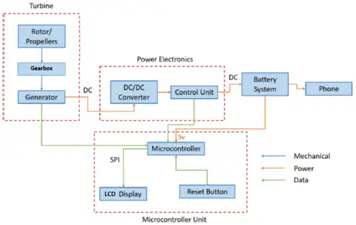
The project comprises three main components: the turbine, power electronics, and microcontroller, with further subsections delineated in Figure 1. The turbine block, inclusive of the rotor and generator, transforms wind power ranging between 5-12 m/s into electric power within a voltage range of 0 to 18V. We consistently employed a specific wind turbine type but made some modifications as needed. Subsequently, the power electronics block receives power from the turbine block. Comprised of a DC/DC converter and control unit, its primary role is to regulate any voltage supplied by the generator to output a stable 5V. The design and construction of the power electronics underwent several adjustments. Initially, it encompassed an AC/DC rectifier and a DC/DC converter, assuming the generator would output AC power.
The microcontroller interfaces with all other blocks, monitoring the generator’s voltage and calculating wind speed, both displayed on a 2×16 LCD screen. Moreover, it draws power from the battery and allocates it to low-power 5V sections of the control circuit. The overall structure of the microcontroller block remained largely unchanged from its initial design. Finally, the auxiliary blocks involve the battery and the phone. While the battery is indispensable, it can be interchanged, as can the phone; neither were specifically designed for this project. In summary, the turbine captures wind energy and delivers 2.5-15W at 5V to a connected battery.
2. Design
Turbine
The turbine serves as the initial stage in the powertrain, transforming mechanical power generated by the wind into electrical power. Comprising two primary components—namely, the rotor and the generator—the former includes rotor blades and rotor bases. The generator, interconnected via a shaft and gearbox, is linked to the rotor.
Outlined in detail in Sections 2.1.1, 2.1.2, and 2.1.3 below are specific design modifications we undertook. An additional alteration, unmentioned in the following sections, pertains to the adjustment of the bottom housing unit. Originally envisioned to be smaller and lighter, the need for stability necessitated sufficient space for the shaft. Furthermore, accommodating the gearbox required extra space, achieved through a belt system, resulting in the need for adequate housing space.
Savonius Rotor
The origin of the Savonius design stemmed from the necessity to develop a wind turbine that was compact, portable, and provided stability. Initial research focused on contrasting “Horizontal Axis Wind Turbines” (HAWT) and “Vertical Axis Wind Turbines” (VAWT). Table 1 highlights the essential distinctions between HAWTs and VAWTs.
Table 1 HAWT vs VAWT Comparison [1]
| Horizontal Axis Wind Turbine (HAWT) | Vertical Axis Wind Turbine (VAWT) |
| Must face wind direction to operate | Omni-directional |
| Requires Yaw mechanism | Does not require Yaw mechanism |
| Equipment is at a height | Equipment is at ground level |
| Self-starting | Generally non-self-starting |
| More efficient at converting wind energy into
electricity |
Less efficient compared to HAWTs |
The VAWT is notably preferable, particularly for our specific usage scenario. Typically, efficiency holds utmost importance in extensive wind farms generating multiple megawatts of power through turbines. However, in our case, the requirement is different as charging a mobile phone demands less than 3 watts of power.
Not mandating a yaw mechanism and positioning the equipment, such as the generator, at ground level proves advantageous for small-scale applications by ensuring portability and minimal user intervention. Although Vertical Axis Wind Turbines (VAWTs) typically lack self-starting capabilities, certain designs deviate from this norm. The imperative need for omnidirectional capability, self-starting functionality, and compactness led to the development of the Savonius design, contrasting with potential stability issues faced by designs like Darrieus due to centrifugal forces exerted on the rotor tips.
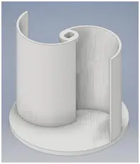
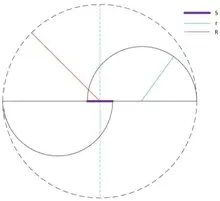
In Figure 3, a bird’s eye view of the Savonius design is depicted. The two semi-circular structures represent the buckets, formed by splitting an 8-inch PVC Schedule 40 pipe. For a comprehensive portrayal of the completed Savonius turbine, please refer to Appendix B. Additionally, Figure 2 offers a visual representation of each individual component.
Each floor undergoes a 90-degree shift concerning the other, meaning the top floor experiences a 90-degree phase shift in relation to the bottom floor. This arrangement enables the Savonius turbine to exhibit omnidirectional capabilities and self-starting functionality. This trait is crucial for a VAWT (Vertical Axis Wind Turbine) as it eliminates the need for external assistance to initiate rotation, thus preserving overall efficiency.
Subsequently, these PVC pipes are positioned on the base components of the rotor. The lower base is designated to accommodate various equipment, including the generator, gearbox, power electronics, and the microcontroller unit. Assembling these components together results in the creation of the turbine.
Below in Figure 4, the correlation between the wind speed accessible and the maximum power derived from the wind is depicted. This correlation embodies the adapted Betz’s Equation, considering that the Betz’s coefficient represents an ideal scenario, whereas real-world implementations deviate from this ideal. Equation 1.1 represents the unaltered Betz’s equation, while Equation 1.2 signifies its modified form.
Equation 1.1
16
???? =
27
????
( ) ????????3
2
[????]
The following calculations are made assuming the following parameters:
Equation 1.2
???? 3
???? = 0.18 ∗ (
2
) ????????
[????]
where ???? = ℎ × ????
Air density, ρ = 1.2 kg/m3
Rotor height, h = 0.5 m
Rotor effective radius, R = 0.4 m (this does not reflect the radius of each specific bucket, it is the
effective swept area radius denoted by R as shown in Figure 3.)
As indicated earlier, the primary factor influencing power output is the wind speed. Given that power increases exponentially in relation to wind speed, higher wind speeds will result in greater wattage.
Moreover, the computations mentioned above are based on a conservative power coefficient of 0.18. Different estimates exist for the specific power coefficient applied, leading to variations in our results based on the actual coefficient utilized [2][3][5].
Generator
Receiving its source power from the propeller, the generator functions to convert the mechanical movement of the blades into electrical energy. Currently, the generator in use is a 36W DC permanent magnet motor capable of operating as a DC generator. Employing a suitable gearing arrangement, the slow rotation of the rotor is transformed into high-speed rotation that the motor can effectively utilize. Following discussions with Professor Haran, it was advised that a permanent magnet motor could be conveniently employed as a generator. Considering factors such as relative availability, size, and cost, this specific motor was selected. With a rating of 36W, this generator aligns with our high-level requirement of achieving 2.5W.
Gearbox
Another pivotal element during the design phase involved the integration of gears. Given the disparity between the operational RPMs of the turbine and the generator, employing gears becomes crucial to mitigate inefficiencies. Table 2 showcases the assortment of gears necessary across different wind speeds. The calculation of the gear ratio was executed utilizing the following approach (considering the generator’s rated speed at 2500 RPM).
Power Electronics
DC/DC Converter
The generator produces unregulated DC, which needs to undergo regulation via a converter to attain an appropriate output voltage for the battery bank. Initially, the DC passes through an input filter. Subsequently, the converter operates as either a buck or a boost, depending on whether the output voltage needs to be decreased or increased. It is crucial for the converter to ensure minimal ripple to ensure compatibility with commercial devices.
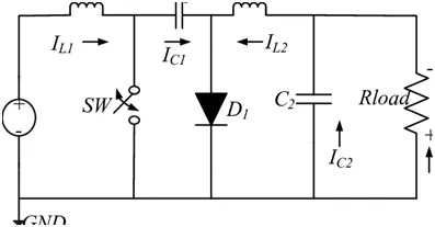
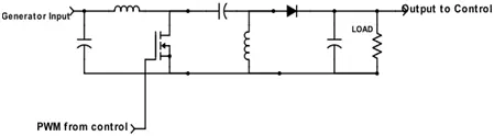
Determining the appropriate topology was the first step. As previously mentioned, the input voltage ranges between 1-18V, while our desired output is 5V. Hence, a topology capable of both buck and boost functionalities was necessary. Initially, a Ćuk topology was chosen due to its simplicity, as depicted in Figure 5. However, the Ćuk’s output is inverted. Initially, attempts were made to work around this inversion, but the control circuit was incompatible with the inverted output. Consequently, a SEPIC topology was selected instead, shown in Figure 6. Notably, this topology involves an additional capacitor and a change in the position of the diode. Alternatively, incorporating an isolating transformer could enhance safety and broaden the range of usable input voltages. However, implementing an isolating transformer might pose challenges, and for our project, the safety aspect is considered unnecessary as the battery pack is equipped with robust protections, and the generator is designed to handle twice the power we intend to maximize.
To confirm that an isolating transformer wasn’t necessary for expanding the voltage range, we utilized a formula to calculate the required duty ratios. It’s essential to note that this duty ratio calculation factors in V(FWD), representing the voltage drop across the diode. Given that high-current-rated components are used for power transmission, the diode’s voltage drop holds more significance compared to low-power applications and must be accounted for.
Once the circuit topology is chosen, determining part values becomes imperative. A fundamental requirement for the converter circuit is to maintain a low ripple voltage. The converter circuit’s output is directly linked to a commercially available battery. Preserving the integrity of the battery is crucial, presuming it was designed to handle outputs from well-established products. Keeping the output voltage ripple at a minimum is essential, with research indicating it should remain below 100 mV peak-to-peak.
The observed ripple at the output is primarily influenced by the output capacitor, particularly the one nearest to the load as depicted in Figure 6. The capacitance value of this component is calculated using the following equation. Additionally, if the capacitor possessed a noteworthy equivalent series resistance (ESR), it could significantly impact the output ripple. Hence, our focus turned to tantalum capacitors due to their favorable size and lower ESR.
Microcontroller
We opted for the ATMEGA32-16PU microcontroller due to its relatively low power consumption characteristics. This 8-bit controller boasts 2 Kilobytes of SRAM, 32 general-purpose I/O lines, and 32×8 general-purpose working registers. Its I/O functionality includes a master/slave SPI and various other features crucial for communicating with the LCD. The multitude of input/output lines proves beneficial as we’ll be gathering data from the generator and providing 5V to control circuit components. Besides providing essential hardware for our project, the ATmega32 microprocessor operates at a clock speed of 1MHz with 3V and consumes merely 1.1mA, aligning perfectly with our generator’s low power requirements. Furthermore, leveraging the fact that the Arduino Uno also employs the ATMEGA32-16PU, we can utilize the Arduino IDE to program the microcontroller for our specific needs.
3. Design Verification
Turbine
Savonius Rotor
As the turbine operates with wind, both natural and/or artificial wind was essential to evaluate the turbine’s voltage output. Various loads were applied to predict its performance when connected to the battery, which mimics an open circuit due to its notably high internal resistance. The table presented below showcases some of the outcomes observed during measurements conducted using a leaf blower to simulate artificial wind generation.
Table 3 Turbine Testing Results
| RPM | Load(Ω) | Voltage |
| 594 | 10 | 4V |
| ~1200 | 50 | 12V |
| ~2500 | Open Circuit | 18+ (Stopped for safety) |
Generator
The generator functioned according to our expectations, successfully converting mechanical power into electrical power through the gearbox. Presented below are the outcomes of the generator, operating under the assumption of no initial losses. However, in practical applications, it is crucial to account for the gearbox’s impact and mechanical losses, as these factors are likely to align the results more closely with those detailed in Table 3.
Table 4 Generator Test Results
| Rotational Speed [rpm] | Empty Load Results | 10Ω Load Results |
| 500 | 4V | 2.5V 0.25A 0.63W |
| 1000 | 8V | 5.5V 0.55A 3W |
| 1500 | 12V | 8.5V 0.85A 7.2W |
| 2000 | 16V | 11.5V 1.15A 13.2W |
| 2500 | 20V | 14.5V 1.45A 21W |
Gearbox
The inclusion of the gearbox in our design was an unforeseen issue. This component acts as the link between the shaft connected to the upper rotors and the generator.
Taking into account the computations within the design phase, our original intention was to employ a gear ratio of roughly 13 to augment the revolutions per minute (rpm) produced at lower speeds, aligning it adequately with the generator’s rated rpm. As this gearbox didn’t allow for variation and maintained a fixed gear ratio, the initial strategy focused on a lower gear ratio. However, due to mechanical challenges, this plan was altered. Eventually, our ultimate gearbox was configured with a gear ratio of 9, aiming to eradicate resistance and subsequently boost our overall efficiency.
Power Electronics
DC/DC Converter
In order to verify the compliance of the converter with its designated specifications, the circuit underwent connection to a DC supply, emulating the generator output. A power resistor was incorporated to simulate the load. Furthermore, a Pulse Width Modulation (PWM) was directed to the MOSFET to replicate the control block’s output. Variations in input voltages were employed, and the output voltage was assessed using both a multimeter and an oscilloscope. The oscilloscope facilitated monitoring of the ripple, while the multimeter provided the measurement of the DC voltage. Across all tested scenarios, the converter consistently achieved the accurate output within the specified ripple constraints, demonstrating high efficiency throughout the evaluations.
Table 5 Converter Test Results
| Input Voltage(V) | Output Ripple Voltage(V) | Efficiency (%) |
| 1.5 | .074 | 71 |
| 2.5 | .073 | 78 |
| 3.5 | .069 | 79 |
| 4.5 | .068 | 79 |
| 5.5 | .070 | 79 |
Control Unit
The functionality of the control unit underwent testing by establishing the appropriate 5V power connections to the circuit and examining specific junctures. Initially, the error generator, the primary step in control, was subjected to testing. An input voltage was directed to the leftmost OP-AMP as depicted in Figure 9 within Appendix C. The other input comprised a 5V reference. A multimeter was affixed to the output of this operational amplifier, and the outcomes were meticulously documented in the table featured in Appendix E. The error output consistently exhibited precision across all values.
Subsequently, validation of the triangular wave was conducted. This validation simply necessitated supplying the requisite 5V to each chip and monitoring the output of the integrating operational amplifier. The diagram in the Appendix E illustration distinctly indicates the accurate generation of the required triangular waveform.
Battery System
The battery performed as anticipated. Challenges arose during the integration process when linking our converter’s output directly to the battery. Yet, by utilizing extra ports, we successfully supplied power to the microcontroller.
Microcontroller
While dealing with the microcontroller circuit, the challenges encountered pertained to shifting the Atmega32-16PU from the Arduino Uno to the breadboard. Upon examining the online schematic of the Arduino Uno, it was noted that the pins associated with the LCD display comprised P0 to P3 for the 4 data inputs, PB2 and PB3 designated for the Enable and R/W lines, and connections for VCC and GND.
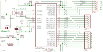
However, upon transferring the Atmega32-16PU to the breadboard following the code upload, the circuit failed to operate correctly, necessitating time to diagnose the issue. After delving into the schematic and datasheet, it became evident that the absence of the 16 MHz crystal oscillator and the two 22 pF capacitors connected to XLA1 and XLA2 was the issue. Despite adding the crystal oscillator, the problem persisted. However, incorporating a basic push button to provide input to the RESET pin enabled the microcontroller to function as intended.
Table 6 Input voltages to Atmega32-16PU for high and low voltages
| Symbol | Parameter | Condition | Units |
| VIL | Input Low Voltage | Vcc= 1.8V – 2.4V | V |
| VIH | Input High Voltage | Vcc= 2.4V – 5.5V | V |
Observing the table provided, it was crucial to ensure the microcontroller received a voltage range between 1.8V and 5.5V for its analog input. This input is intended to measure the voltage output from the generator. To achieve this, a voltage divider utilizing resistors of 100 Ω and 30 Ω was employed to reduce a 20V voltage to approximately 4.62V. This allowed the microcontroller to safely read the analog value without risking damage to any components within the circuit.
- How does the turbine capture wind from any direction?
The turbine uses a two-level Savonius design where the top floor is shifted 90 degrees relative to the bottom floor, providing omnidirectional capability. - What type of generator is used in the project?
A 36W DC permanent magnet motor is used as the generator to convert mechanical movement into electrical energy. - Why was the SEPIC topology chosen over the Cuk topology?
The SEPIC topology was selected because the Cuk output is inverted, which made it incompatible with the control circuit. - Can the microcontroller calculate wind speed?
Yes, the microcontroller oversees the generator's output to calculate wind speed and displays both values on the LCD screen. - What is the maximum power output of the device?
The wind turbine phone charger is designed to deliver a maximum of 15W of power to a battery pack. - How is the low rotation speed of the rotor handled?
A gearbox is employed to transform the slow rotation of the rotor into high-speed rotation suitable for the generator. - What component ensures minimal ripple voltage at the output?
Tantalum capacitors are used near the load to maintain low ripple voltage, keeping it below 100 mV peak-to-peak. - How is the microcontroller powered?
The microcontroller draws power from the battery and allocates it to the low-power 5V sections of the control circuit.