Summary of Wireless Persistence of Vision Device with Realtime Control Using Atmega644
This article details the design of a modular, wireless Persistence of Vision (POV) display using an Atmega644 microcontroller. The project features a 2D RGB LED array driven by MAX6971 chips, controlled via XBee wireless serial communication and a Java GUI. Key engineering challenges included managing high current draw with dual power supplies, designing custom "brushing" for rotating power transfer, and mitigating vibration issues through base weighting and damping. The system supports both ROM-controlled animations and direct real-time control.
Parts used in the Wireless POV Display:
- Microcontroller (Atmega644)
- Motor
- AC to DC wall wart (5V 2.5A)
- AC to DC wall wart (9V 1.1A)
- Linear regulator 5V (LM7805CT-ND)
- Linear regulator 3.3V (296-21611-5-ND)
- XBEE wireless transceiver
- XBEE to USB board
- LED driver (MAX6971)
- EEPROM 1MB (25AA1024)
- 4x2:1 mux (74ACT257SC-ND)
- PCB board for control board
- PCB board for 2D display
- RGB LEDs
- Resistors (10k and 150 ohm)
- Capacitors (.1uF, 15pF, 4.7nF, .33uF, 33uF)
- Crystal oscillator (16Mhz)
- Hall sensor (US5881EUA-ND)
- Inductor (68uH)
- Base to board brushing
- Motor to board connector
- Switches
- Base
- Connectors 2x36 female 2mm
- Connectors 2x36 male 2mm
Introduction
We set out to make an easy to interact with, highly custimizable POV display.
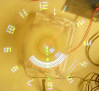
In deciding on a project we looked for a challenge that would have a good mix of hardware and software problems. We ended up primarily concentrating on looking at unusual display technologies and decided that a persistence of vision(POV) display would be a good balance. A POV display is a display created by rotating an array of LEDs rapidly. Due to the fact that human eyes can only render so many images per second, the fast spinning LEDS seem like a solid display.
While many POV projects have been designed before, they tend to be very static. Often they only display one image or animation and usually have no interactivity. We set out to make a very modular multipurpose design. Our original goal was to make two different LED arrays, a 2D version with RGB LEDs and a 3D version that uses monochrome LEDs. While we only had time to make the 2D display, our design makes it easy for the user to swap the LED array for a different one. Additionally, our design is fully customizable. Images can be uploaded and managed from a computer connected wirelessly, as can the firmware.
High Level Design
We found the idea for the persistence of vision device (also known as a propeller clock) here.
To improve upon the device we found, we wanted a way for the propeller clock to communicate with a computer and decided to use the serial protocol for this. At the same time, we decided to make a friendly GUI with JAVA so that any user can intuitively do the updates. The serial interface that we ended up using is the XBee. This device was extremely helpful since it allows us to have wireless serial communication. At the same time it is also extremely easy to use. They work right out of the box and only needs to be plugged into the laptop and our device.
In order to make our multipurpose propeller clock, we decided to make two main components. The main circuit board will do all the calculations necessary to figure out what LEDs to turn on while the secondary board will only have LEDs. This would make it extremely simple to switch between the 2D vs 3D propeller clock that we envisioned. The main circuit board is also unique since it can either read data from the external EEPROMs (rom control) or be controlled directly (direct control). This gives us a lot of versatility. Rom control makes animations simple to do while the direct control allows us to display a clock, dynamically generated messages (Gaming capability is also being looked at). More details on how this all works can be found under Hardware Design.
Hardware Design
Power
Power was a major issue in our design. Since we need to power a motor and also 32 RGB LEDs (96 individual LEDs), the current being drawn is tremendous. As a result, we decided to use two power supplies to power the motor and the LEDs. Another reason why we did this is because two separate power sources get rid of the noise that might have occurred if the motor power supply was used to power the LEDS as well.
The total current needed by the microcontroller unit, the EEPROMs, and the LED drivers is about 450mA from the 5V regulator. The XBee that we use for the wireless communication takes about 50mA from a 3.3 linear regulator. The LEDS take about 173mA from a 9V power supply. This means that we need to draw about 673mA in order for the PCB boards to work. This number was actually even higher in our originally calculations since the datasheet on the LEDs said that they each need about 10mA (2mA ended working just as well), or 960mA for all 96 to turn on.
That would have meant the total current being drawn would have been around 1500mA. This makes battery power not feasible. Duracell batteries have a 0.83amp-hour rating at 1A current draw, so the batteries would have died way too quickly. As a result, we decided to use a brushing system to supply the power which is explained in more details under brushing.
Essentially to power the PCB boards, a power adapter is used to pass 9V (1.1A rating) to the spinning board. The 9V goes straight to the LEDs and the 5V regulator. The regulator goes through a PI filter and then to a 3.3V regulator and the rest of the 5V devices. The PI filter ensures that slight current variations caused by the noisy brushing are removed. As a result, we never had any brownouts except for when the brushing fails (explained in more detail below). The motor has its own independent 5V (2.5A rating) power supply so there was no problem there.
Costs
Budgeting was also an issue since we are only allowed to use $70 in addition to what we have lying around. Our design requires many connections between multiple devices, so it was impossible to do by hand to get the small form factor we needed. At the same time, custom made PCB boards are expensive. On top of that, since we wanted a modular design, we needed two PCB boards. To minimize cost, we decided to get a custom made main board and etch the LED PCB board by ourselves. More details can be found under PCB board.
Motor System
A working motor system is critical for our success. For one, it must spin fast enough so that we can get at least 10 frames a second. Lower rotation speed will make images unrecognizable. Extremely good images require 15 30 frames per second, but since we have a spinning device, the higher rotation speed can be dangerous. As a result, we usually tried to use the lowest speed possible.
Brushing
As you can see from the picture below, the motor assembly design is relatively straight forward. However, perfecting the brushing took a long time and it was main cause of our headaches. For awhile, we werent even able to test our code since the brushing was constantly losing contact or shorting
The brushing for the ground was relatively easy to make. We just took some metal bristles from a barbeque grill cleaner and used that to contact the motor shaft. This causes the connector(custom made screw) to be grounded. Also, since the connector between the PCB board and the motor is metal, the connectors head always end up touching the grounded bristles as well.
If you want to read about the different designs we had to go through to get the power brushing to work, click HERE.
In our final version, the power brushing was made entirely out of a single spring that we took from a pen and some wet noodle. We used a lot of hot glue so that relatively little spring would be exposed so that it wouldnt get knocked over too easily. At the same time, we wrapped some Wet Noodle wire around the end of the spring that we straightened. This results in extremely good contact(more surface area due to the straight part) and low friction. To reduce friction even further, we put some motor oil on the wet noodle tip.
In addition to all that, we also need to insulate the power brushing from ground. The connector is grounded, but due to a lack of space the power brushing is only 1 mm away. We resolved this by wrapping the sides of the connector with electrical tape and filling in the gaps at the base of the tape with wood glue (Thick, non instant glue is best). In addition, to prevent the power brushing from going out of its boundaries, we boxed it in with some wire.
Connector
We machined our connector(screw) in the Cornell machine shop. Since our motor has a flat edge on the motor shaft, it gives the worm screw on the side of the connector a lot of grip. We made the connector longer so that we could secure it to the PCB board with a nut. A picture of this is shown below. When making this connector, we had to take into account that our modular design doesnt give the connector much clearance. If the connector was too high, it would hit the PCB board right above it (A LED will always be at the center of the board, or right above the connector).
Vibrations
We had some major vibration issues in the beginning. At times, it felt as if the PCB board would fly off due to the imbalance of the spin. We fixed this in various ways. We increased the weight of the base so that it wouldnt move around as much. At the same time, we put the base on top of foam pads to dampen the vibrations. In addition, we secured the motor more firmly onto the actual metal base. Finally, we balanced the PCB board in all directions so that the center of mass wouldnt shift around.
PCB Board
The heart and soul of this project lies with the PCB board. The modular design will be explained below and pictures of our design are at the end of this section.
Main Board
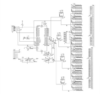
On our main board, the current layout for how the microcontroller pins are used is as follows: PORTA is not used at all, PORTB is used for the SPI and for the test LED (PB0), PORTC is mainly used for direct control of the LED drivers when the board is in direct control mode. Each pin corresponds to a different driver. PORTD is used for USART (GUI / bootloader) control, EEPROMS(CS), and input from the hall sensor
Based on other designs, we selected these values for the components shown in the schematics below: a)10k ohm resistor: pull up resistor and current control for drivers b)0.1uF capacitor: decoupling capacitor c)15pf: Clock capacitor c)150ohm resistor: LED current control d)Red LED/Test LED: test/heartbeat LED e)Crystal: 16Mhz Clock Oscillator f)Hall Sensor: Detects Rotations g) 4.7nF: Hall Sensor Capacitor h)0.33uF Power Input Filter i)68uH inductor: part of 5V line pi filter j)33uF: part of the 5V line pi filter.
LED Control
The LED’s are directly controlled by MAX6971 LED drivers. These drivers are able to turn the LEDs on by sending a preset current to them which is calculated with the equation I = 18/Rset. This equation is given in the datasheet and Rset is the resistor that we use to connect the SET pin to ground. Initially we used 1.8k resistors to give the LEDs 10mA, but they were far too bright to view. After some testing, we found that 10K resistors got the brightness down to a decent level.
This means that the LED’s were getting 1.8mA each, so the final current drawn by all 96 LEDs is 173mA. We store the LEDs on off state in a register with each bit corresponding to an LED in their shift registers. However, the LED states are only updated from this register when the Latch enable pin is high in order to prevent LEDs from switching states in the middle of a frame.
Our MCU has two mechanisms with which to control the LEDs, one of which is direct control. Here the shift-in pin of each driver is connected to one of the eight pins of PORTC. The serial clock is controlled by PORTB7. A single bit in all eight drivers is set simultaneously by pulsing PORTB7 to feed in the PORTC values. This means that it takes a minimum of 4 cycles (mem load,PORTB toggle, set PORTC, PORTB toggle) to update a bit or about 4*16=64 cycles to update all the LEDs.
Parts List:
| Part Name | Description | Amount | Seller | Part # | Cost | Refdes |
| Microcontroller(atmega644) | processor | 1 | Atmel | ATMEGA644-20PU | sampled | U1 |
| Motor | motor to spin board | 1 | NA | NA | salvaged | NA |
| AC to DC wall wart (5V 2.5A) | power supply for motor | 1 | NA | NA | salvaged | NA |
| AC to DC wall wart (9V 1.1A) | power supply for LED’s and logic | 1 | NA | NA | salvaged | NA |
| linear regulator 5V | 9V to 5V regulator for logic besides XBEE | 1 | digikey | LM7805CT-ND | $0.45 | U5 |
| linear regulator 3.3V | 5V to 3.3V for XBEE | 1 | digikey | 296-21611-5-ND | $0.84 | U10 |
| XBEE wireless tranciever | wireless data link to computer | 1 | digi | NA | already owned | CONN1 |
| XBEE to USB board | Computer side transciever | 1 | digi | NA | already owned | NA |
| LED driver | shift register and power control to LEDs | 8 | maxim | MAX6971 | sampled | U(3,6,9,11,12,14,15,17) |
| EEPROM 1MB | EEPROMs for storing image data | 4 | microchip | 25AA1024 | sampled | U?’s |
| 4×2:1 mux | mux to choose between driver shift out and direct control | 1 | digikey | 74ACT257SC-ND | $0.40 | U8 |
| PCB board for control board (3×6″) | PCB with all circuitry except LEDs | 1 | sunstone | NA | $20.00 | NA |
| PCB board for 2D display | a modular plug in board with LEDs | 1 | we made | NA | $6 | NA |
| RGB LEDs | LEDs for RGB board | 32 | mouser | 828-OVSRRGBCC3 | $25 | NA |
| 10k resist | pull up resistors and current control for drivers | 14 | digikey | 311-10.0KCCT-ND | lying around | R(1,3,4,5,6,7,8,9,10,11,12,13,14,15) |
| .1 uF cap | decoupling capacitors | 3 | digikey | 311-1140-1-ND | lying around | C(1,3,4) |
| 15pF | clock capacitors | 2 | digikey | 709-1170-1-ND | lying around | C(5,6) |
| 150 olm resist | LED current control | 1 | digikey | P150ACT-ND | lying around | R2 |
| red led | test/hearbeat LED | 1 | digikey | 160-1178-1-ND | lying around | LED |
| crystal | 16Mhz clock occilator | 1 | digikey | 631-1024-2-ND | lying around | U2 |
| hall sensor | detects rotations | 1 | digikey | US5881EUA-ND | 1.93 | SEN |
| 4.7nF | hall sensor capacitor | 1 | digikey | 399-1155-1-ND | $0.04 | C2 |
| .33uF | power input filter | 2 | digikey | P822-ND | lying around | C(7,11) |
| 68uH inductor | part of 5V line pi filter | 1 | digikey | 308-1341-1-ND | $1.03 | L1 |
| 33uF | part of 5V line pi filter | 3 | digikey | P815-ND | lying around | C(9,10) |
| base to board brushing | needed to transfer power to spinning board | 1 | we made | NA | scraps | NA |
| motor to board conector | mechanical connection between board and motor | 1 | friend made | NA | friend didn’t charge | NA |
| switches | switches to turn on board and motor seperately | 2 | NA | NA | lying around | NA |
| base | base to put motor on | 1 | NA | NA | scraps | NA |
| connectors 2×36 female 2mm | connectors to modulorize boards | 16 | samtec | SMM-136-02-S-D | sampled | CONN2-5 |
| connectors 2×36 male 2mm | connectors to modulorize boards | 8 | samtec | TMM-136-01-T-D | sampled | NA |
| Total | $55.33 |
For more detail: Wireless Persistence of Vision Device with Realtime Control Using Atmega32
- What technology does the device use to create images?
The device uses persistence of vision by rotating an array of LEDs rapidly so human eyes perceive a solid display. - How does the device communicate with a computer?
It uses the XBee wireless serial transceiver to communicate wirelessly with a computer running a Java GUI. - Why were two separate power supplies used?
Two supplies were used to power the motor and LEDs separately to handle high current draw and eliminate electrical noise from the motor affecting the LEDs. - Can the device display dynamic messages or just static images?
Yes, the design allows for direct control to display clock faces, dynamically generated messages, and potentially gaming capabilities. - What was the primary cause of difficulty during the project?
Perfecting the power brushing mechanism was the main cause of headaches as it frequently lost contact or shorted before the final design. - How did the team resolve vibration issues?
Vibrations were fixed by increasing the base weight, using foam pads, securing the motor firmly, and balancing the PCB board. - What resistor value was found to be best for LED brightness?
Initially 1.8k resistors were used but they were too bright; 10k resistors were found to provide a decent brightness level. - Does the device support modular LED arrays?
Yes, the design is modular, allowing users to swap the 2D RGB board for a different array like a 3D monochrome version.