Summary of Working with the Comparator Circuit
This article explains the function of comparator circuits in embedded systems, highlighting their role in converting analog signals to digital outputs when thresholds are exceeded. It contrasts comparators with operational amplifiers (Op-Amps), noting that comparators offer faster switching times for digital logic. The text details the LM339 quad comparator's open-collector output structure, requiring a pull-up resistor, and provides a calculation example for setting a reference voltage using a resistor divider.
Parts used in the Comparator Circuit:
- National Semiconductor LM339 quad comparator
- LM324 quad Op-Amps
- Open collector transistor Q8
- Pull-up resistor
- Resistor R1
- Resistor R2
- 5 Volt voltage supply
Sometimes in the embedded system world we need to process the analog world and sending the signal to the microcontroller when the analog signal exceed some predetermine limit we’ve set. Some example of this situation is to send the interrupt signal to the microcontroller operation when the temperature is already exceeds certain limit or the light intensity exceeds certain bright level. This is when the comparator circuit becomes handy as it’s designed specially for this purpose.
Today the modern comparator is easily found in the form of integrated circuit such as the popular National Semiconductor LM339 quad (four) comparator 14 pins dual in line (DIL) package bellow: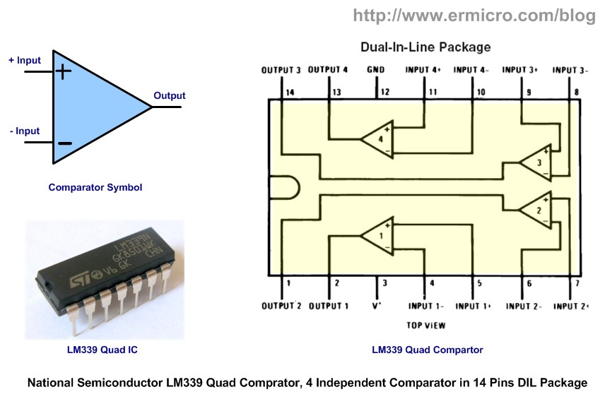
When you look closely to the comparator symbol, some of you will recognize it as the Op-Amp (Operational Amplifier) symbol, so what make this comparator differ from its big brother; Op-Amps is designed to accept the analog signal and outputting the analog signal while the comparator only outputting the digital signal; although the ordinary Op-Amp could be used as the comparator such as the popular National Semiconductor LM324 quad Op-Amps, but the real comparator is designed to have a faster switching time comparing to the multipurpose Op-Amps. Therefore you could say that the comparator is the modified version of the Op-Amps which specially designed to give the digital output.
1. Basic Comparator Circuit
The comparator circuit work by simply taking two analog inputs, comparing them and produce the logical output high “1” or low “0“.
By applying the analog signal to the comparator + input called “non-inverting” and – input called “inverting“, the comparator circuit will compared this two analog signal, if the analog input on + input is greater than the analog input on – input (inverting) then the output will swing to the logical “1” and this will make the open collector transistor Q8 on the LM339 equivalent circuit above to turn ON. When the analog input on + input (non inverting) is less than the analog input on – input (inverting) then the comparator output will swing to the logical “0” (the Q8 transistor turn OFF). Furthermore on this tutorial, I will use the term non-inverting and inverting instead of + input and – input on the comparator analog input.
As you’ve seen from the LM339 equivalent circuit picture above, the LM339 use an open collector transistor Q8 for its output, therefore we have to use what is called “pull-up” resistor connected to the Q8 collector lead with the Vcc in order to make this Q8 transistor work. The maximum current that could flow on this Q8 transistor (output sink current) according to the LM339 datasheet is about 18 mA.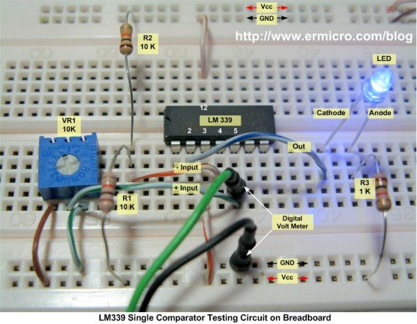
The testing circuit simply connects the comparator inverting input to the voltage divider R1 and R2, with 5 Volt voltage supply the V- could be calculated as follow:
V- = (R2 / (R1 + R2)) x Vcc
V- = (10 / 20) x 5 volt = 2.5 volt
For more detail: Working with the Comparator Circuit
- What is the primary difference between a comparator and an Op-Amp?
A comparator outputs a digital signal while an Op-Amp outputs an analog signal. - Why is a real comparator preferred over an ordinary Op-Amp for this task?
Real comparators have a faster switching time compared to multipurpose Op-Amps. - How does the comparator determine its logical output?
If the non-inverting input is greater than the inverting input, the output swings to logical 1; otherwise, it swings to logical 0. - Why is a pull-up resistor necessary for the LM339?
The LM339 uses an open collector transistor output, requiring a pull-up resistor connected to Vcc to function. - What is the maximum output sink current for the LM339?
The maximum current that could flow on the output transistor is about 18 mA. - How do you calculate the voltage at the inverting input in the example circuit?
You use the formula V- = (R2 / (R1 + R2)) x Vcc. - Can an Op-Amp be used as a comparator?
Yes, an ordinary Op-Amp like the LM324 can be used, though it is not designed specifically for this purpose. - What happens to transistor Q8 when the non-inverting input is less than the inverting input?
The Q8 transistor turns OFF, causing the output to swing to logical 0.