Summary of ZYBO OV7670 Camera With Pan/tilt Control
This article details the creation of a 2-axis servo PWM controller using a Digilent Zybo board and Vivado. The process involves setting up a ZYNQ7 Processing System with two AXI Timer IPs to generate PWM signals for pan and tilt control. Key steps include configuring block designs, assigning pin constraints via an XDC file, and connecting TowerPro SG90 servos through a Pmod CON3 interface. The guide also covers generating bitstreams and launching the SDK for hardware deployment.
Parts used in the 2-axis servo PWM controller:
- Digilent Zybo Board
- Pmod CON3 from Digilent
- TowerPro SG90 Servo Motor
- Vivado Design Suite (Version 2017.2)
- Zybo-Master.xdc Constraint File
- Camera + Pan/tilt setup (Amazon B013JF9GCA)
Start at step one for detail on just creating an 2-axis servo PWM controller.
Start at the massive block diagram (Step 19) for the full project.
Camera + Pan/tilt setup we used: https://www.amazon.com/gp/product/B013JF9GCA
The PmodCON3 from Digilent was used to connect the servos.
Step 1: Building a PWM Module- Source File
Step 2: Building a PWM Module- Vivado Setup
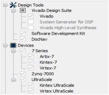
First, download the Vivado Design Suite From Xilinx website. Install all the design suite, including Vivado Software Development Kit(SDK). This project uses 2017.2 version.
In the meantime, Digilent Adept 2 should also be installed as a Zybo board driver.
Step 3: Building a PWM Module- Create a Project File
Before creating a project file, you should ensure that you’ve already installed the Zybo file properly as the tutorial here:
Vivado Version 2015.1 and Later Board File Installation
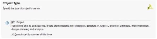
Open Vivado 2017.2. On Quick Start, click on Create Project -> Next -> Project Name(Name your project name here) -> Project Type. On Project Type, select RTL Project and mark on “Do not specify sources at this time”. Next, for the Default Part, select “Boards” and “Zybo” as Display Name. Next, Click Finish to start the project.
Step 4: Building a PWM Module- Block Design and Constraint File Setting (I)
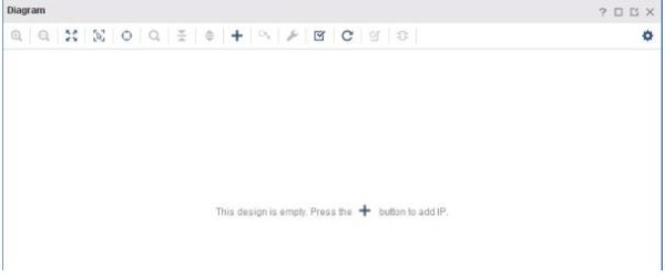
On Flow Navigator, click on “”Create Block Design”, then press OK. click the “+” sign to add necessary IPs. Add:
- One ZYNQ7 Processing System Two AXI Timer
- Two AXI Timer
Step 5: Building a PWM Module- Block Design and Constraint File Setting (II)
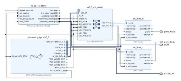
After Adding IPs, Run Block Automation and connection automation. Once the automation is completed, on the block “axi_timer_0”, right click on pwm0 -> Make External. Name the pwm0 external pin as pwm_Xaxis. Also, repeat the above process on the block “axi_timer_1” and name the pwm0 external pin as pwm_Zaxis.
Step 6: Building a PWM Module- Block Design and Constraint File Setting (III)
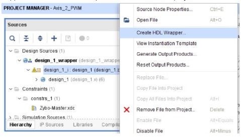
Notice that every time when we finish the Block Design in Vivado, we need to create an HDL Wrapper. Since it will be the top-level module for each project.
Step 7: Building a PWM Module- Block Design and Constraint File Setting (IV)

Now, we need to set up our constraint file to assign pins connected to our block diagram. Close the Block Design window, On Sources tab, “Add Sources”->Add or create constraints-> add the Zybo-Master.xdc as our constraint files.
Step 8: Building a PWM Module- Block Design and Constraint File Setting (V)
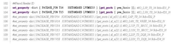
Open the constraint file Zybo-Master.xdc from Constraints folder, uncomment the ports we want to specify as output signals and rename “ get_ports{XXXX}”, which XXXX denotes the external pin named in the Block Diagram. The setting of constraint file is shown in the figure.
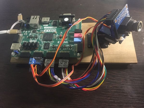
Step 9: Building a PWM Module- Hardware Installation
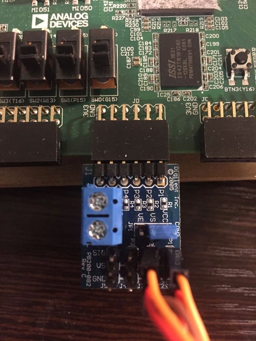
Connect the servo motors to the Pmod CON3. TowerPro SG90 is the servo motor model we used in this project. For the servo motor wires, the orange wire represents the PWM signal, connected to SIG pin in Pmod CON3. The red wire Vcc is a power wire connected to VS pin in Pmod CON3. Finally, the brown wire Gnd is a ground wire connected to GND pin. Next, insert the Pmod CON3 to the upper row of JD port in the Zybo Board.
Step 10: Building a PWM Module- Generate Bitstream and Launch SDK
1.In the Project Navigator tab, run Generate BitStream.
2.Export hardware: File > Export > Export Hardware-> mark on “include bitstream”-> OK 3.Launch SDK : File -> Launch SDK.
Source: ZYBO OV7670 Camera With Pan/tilt Control
- Which version of Vivado is recommended for this project?
The project uses the 2017.2 version of the Vivado Design Suite. - How do I connect the servo motor wires to the Pmod CON3?
The orange wire connects to SIG, the red wire to VS, and the brown wire to GND on the Pmod CON3. - What IP blocks are required for the Block Design?
You need one ZYNQ7 Processing System and two AXI Timer IPs. - How are the PWM output pins named in the Block Design?
The external pins are named pwm_Xaxis for the first timer and pwm_Zaxis for the second timer. - Where can I find the constraint file for the Zybo board?
The tutorial specifies adding the Zybo-Master.xdc file as the constraint file. - What steps are needed before creating the project file?
You must ensure the Zybo board file is properly installed following the specific tutorial instructions. - How do you export the hardware for the SDK?
Select File > Export > Export Hardware and mark the option to include the bitstream. - Which servo motor model was used in this specific build?
The TowerPro SG90 servo motor model was used in this project.