Introduction
Our project, in one sentence, is an orientation independent 3D LED display. We were inspired by various videos on youtube of similar cubes but also by the idea of creating an interactive 3-dimensional display.
We built a 5x5x5 LED cube display and controller board which interfaced the cube to a Mega32 microcontroller. We can display a wide range of low resolution 3D images or animations on our cube and we use an accelerometer to detect the horizontal or vertical orientation of the cube and adjust the display so that it remains upright even if we turn the cube sideways. The cube was used to display a message (“ECE476 FINAL PROJECT DEMO”) and display a little light show animation.
High Level Design
We received inspiration for our design when we saw one of the many videos on youtube of 3D LED cubes. We thought the idea of a 3D display was interesting yet challenging given the budgetary and time constraints and we also thought we could take the idea one step further (this extra step ended up being the orientation adjustment using an accelerometer).
One of the main considerations when first designing our cube was deciding how large to make it. Obviously more LED’s would give better resolution and allow us to display some more interesting images but at the same time we were limited by how large of a cube we could fabricate in the given time and even more so by how many LED’s we could reasonably control given the limited number of port pins and the limited processing power of the Mega32. We eventually settled on a 5x5x5 cube as a reasonable trade off between size and practicality, however, we do invite future groups, and others interested, to attempt to build a bigger cube given similar time and budget constraints (we suggest 8x8x8 since it gives you a nice round 512 LED’s).
The next major consideration was how we would control all of the LED’s. A 5x5x5 cube made for 125 LED’s which was far more LED’s than ports on the Mega32. We originally developed a method of controlling each LED individually that is much like the method used in common LED drivers. The method involved sending a serial bit stream that represented the state of each LED into a 125 bit serial-in parallel-out shift register. After shifting in the state of each of the 125 LED’s we would then latch the value of each bit using 125 flip flops and drive each LED off of the output of a flip flop. This method required only 3 ports pins (one for the serial bit stream, one to clock the shift register, and one to clock the flip flops) and was very fast since we could clock the shift register at upwards of 1 MHz and theoretically update all the LED’s in a couple hundred microseconds. Theoretically this method seemed very fast, however, practically this method was extremely inefficient.
The main problem with controlling each LED individually was that to do so we would need to run at least 1 wire to each and every LED. This problem quickly got out of hand; at the bottom of the cube we would have at least 6 wires running off of each of the 25 columns. All of these wires would have made for an aethstetically unpleasing cube and present the question of how we would route all these wires together and fit them into the base of the cube. We realized we would need to wire the LED’s together in a way that we could address them individually without having to run a separate wire to each one. This was a tricky problem since a typical addressing scheme such as selecting a column, then a row, then a level would have the undesirable side effect of lighting more LED’s than we wanted.
After some thought and search, we finally found this website which gave us a great method of how to do it. The tutorial showed us that we could in fact address LED’s one at a time without having to run a ton of wires. To do so we would connect all of the up and down columns of LED’s to the same positive terminal (25 columns total, with 5 LED’s each) and then connect all of the horizontal levels to the same ‘ground’ (5 levels with 25 LED’s each). To select a single LED we would apply 5V to the column in which the LED is located and then ground the level that it is on. This way using only 25 control lines for the columns and 5 control lines for the grounds we could select each LED individually. However, this still results in the previous problem of lightning extraneous LED’s accidentally if we try to light more than 1 LED at a time. As illustrated in Figure 3, if we wanted to light just the first LED in the top level (back left corner) and the last LED on the bottom level (front right corner) we would set the 1st and 25th columns high and then ground the top and bottom levels. However, if we do this, instead of just having 2 LED’s lit we would have 4 (top and bottom of back corner and top and bottom of front corner). To get around this we only try to light LED’s in one column at a time. To display images that have LED’s from multiple columns lit we cycle through each column at a fast rate (about 62.5Hz) to make it appear as though more than one column of LED’s is on at the same time.
Program/Hardware Design
Hardware Description
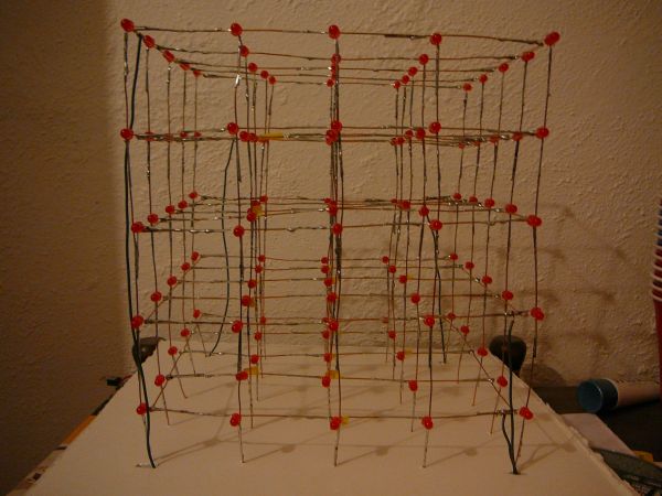
There was a lot of circuitry that had to be constructed in order to realize this project. First, we had to build the LED cube itself which actually turned out to be a much more difficult task then we first anticipated due to the shear number of LED’s. We built each horizontal 5×5 plane individually by laying the LED’s flat on top of wire and soldering all the negative terminals of the LED’s onto the wire and leaving the positive terminal hanging. This essentially connected all the negative terminals of the LED’s in the same level to the same ground plane. We then had to carefully solder the 5 horizontal planes together by first mounting them on the side of a cardboard box and taping them into place in a upright position and then soldering 1 wire to connect all the LED’s in a vertical column together for each of the 25 columns.
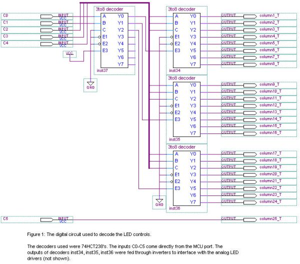
In addition to building the LED cube itself we also had to design and build our own custom LED driver circuit. This circuit had to take inputs from a limited number of microcontroller pins and decode them into something that could control the cube. If we had simply taken the input of each column and each ground level directly from a microcontroller pin this would have taken 30 pins which would have taken up most of the 32 port pins of the Mega32 microcontroller. This would have been alright for our final application (which only needed two extra pins for the accelerometer input) but would make it hard for future projects to utilize our design. Instead, we decided to come up with a clever way to decrease the bus size and simplify the interface between the driver and the microcontroller.We created a decoding circuit (Figure 1) that could control 24 columns using only 5 pins. The remaining 25th column and the 5 ground levels were controlled directly from the microcontroller; this resulted in using a total of only 11 pins to control the entire cube.
The first two bits of the 5 control lines feed into the first decoder (inst37). This decoder acts as a control that can select to enable any one, and only one, of the other 3 decoders. There is also a fourth option in which none of the output decoders are enabled which we use as a way to turn off all the LED’s in the cube. The remaining 3 control lines feed into the 3 output decoders (inst34, inst35, and inst36). The outputs of these decoders feed directly to the columns; since only one output of any given decoder is high at a time, and only 1 of the output decoders is enabled at any given time, it is only possible to turn on 1 column at a time. This is highly favorable because, as shown in Figure 3, attempting to drive more than one column high at a time results in the unwanted lighting of additional LED’s. Basically using this decoding scheme we can select any of the first 24 columns simply by sending the binary number of the column (the top two bits being a control for the master decoder and the bottom three being the input to the selected decoder).
After completing the design of the digital circuit we were ready to connect it to our LED cube, however, before we did, we realized a glaring problem. The output from each pin of each decoder was to drive an entire column of LED’s. This meant driving as many as 5 LED’s in parallel, each drawing around 40 mA of current (Figure 4), for a total of 200 mA of current, however, the maximum current output of the decoder chips was rated at only 25 mA which would not be enough to drive even 1 LED, let alone all 5. Additionally, the port pins of the microcontroller were originally going to serve as the ground plane for all the LED’s but we realized that they could in no way sink the amount of current that we needed to sink. To account for this we had to design a LED driver circuit which still used the outputs of the decoders and the microcontroller to control each column and the ground planes but drove the LED’s through an external power and ground.
To control the LED’s using the outputs of the decoders we used 25 pMOS transistors as high side switches and 5 nMOS transistors as low side switches (Figure 2). The pMOS transistors use the output of the decoder circuit as a sort of enable and supply the LED’s with 5V when they are turned on. However, since pMOS transistors turn on with a low gate to source voltage, and the decoders we used were active high, we had to feed the output of the decoders through inverters before we connected them to the transistors. In a similar way the MCU ports are used to control nMOS transistors that connect the LED’s to ground, however, since the control comes directly from a port pin there is no need for inverters here. Another problem that we encountered involved the amount of current that we could drive. The power now comes directly from a 5V regulator that is rated to supply at least an amp of current, which was more than enough, but the pMOS transistors that we used are only rated to supply 160 mA of continuous current. This meant that we would still have trouble driving all 5 of the LED’s at the same time since each of the 5 LED’s would try to draw 40 mA of current for a total of 200 mA. In order to get around this we employed a trick in the software that, instead of turning on all 5 LED’s at the same time, would turn on the bottom 3 LED’s first and then turn on the top 2 LED’s.
Another concern, that is a direct consequence of our lighting scheme, is the timing. Since we need to strobe through a series of LED’s to make it appear as though more than one LED is on at the same time we had to be careful about the amount of time that it takes to cycles through all of the LED’s (refresh rate) and the time that we hold each LED on for (duty cycle). We wanted to try to keep each LED on for as long as possible since a longer duty cycle would make for brighter LED’s. However, holding each LED on for longer would mean that it took more time to cycle through all the LED’s and if this refresh rate was too slow then you could see a noticeable flicker. After some testing we decided that we wanted to cycle through all the LED’s every 16 ms giving us approximately a 62.5 Hz refresh rate and eliminating any visible flicker. This meant that in 16 ms we would need to cycle through all 25 of our columns and for each column, hold the bottom three LED’s that are currently lit on for a time, turn them off, and then hold the top two. We found that we could hold each of the 50 sets of LED’s (top and bottom of each of the 25 columns) on for 200 μS and still meet our refresh rate requirements; each “frame” would take 10 ms to render leaving us with 6 ms of grace time to perform any necessary calculations for the next frame.
Parts List:
| Part | Quantity | Price |
|---|---|---|
| Mega32 Prototype Board | 1 | $5.00 |
| Mega32 Socket | 1 | $0.50 |
| 74LS04 Hex Inverter | 6 | $3.42 |
| CD74HCT238 3-8 Decoders | 4 | Sampled |
| SOIC Breakout Board | 4 | $4.00 |
| Red LED (LEDTECH UT1841R-81) | 125 | $5.00 |
| Freescale Battery Clip 3/5 Volt Regulator | 1 | Sampled |
| Freescale MMA6261Q Accelerometer Board | 1 | Sampled |
| LM340T5 1A 5V Regulator | 1 | $1.66 |
| Large Protoboard | 1 | $2.50 |
| Medium Protoboard | 1 | $1.00 |
| zvp3306a Transistor | 25 | $5.95 |
| zvn3306a Transistor | 5 | $1.45 |
| Header machine pins | 100 | $5.00 |
| Atmel Mega32 Microcontroller | 1 | $8.00 |
| Foam Board | 1 | $6.00 |
| 9V Battery | 1 | $2.00 |
| Thick guage wire | 3 Rolls | Free (Pre-owned) |
| Various Resistors, Capacitors, and Wire | – | Free (Lab) |
| Total | $51.48 |
For more detail: 5x5x5 LED Cube – Orientation Independent 3D Display Using Atmega32